THAT1512 based pre

GroupDIY Audio Forum

Help Support GroupDIY Audio Forum:

This site may earn a commission from merchant affiliate links, including eBay, Amazon, and others.
[quote author="PRR"]Off-topic: MCS, I want to thank you for preserving the "Improving Williamson" article. I read that when it was nearly new, and thought it was an excellent analysis of an excellent design. I'm not sure I now agree with every opinion and detail, but it is still very worth the time to read. [/quote]
Fell free to add your opinions on the details :grin:
- I have a Williamson monster here somewhere...

In an idle moment, I collected the three page-scan images into one file, ImprovingWilliamson.PDF, about 290KB. This may be a little easier to re-size and print. Feel free to grab it.
It looks like you reduced the resolution a bit? Here's a full-resolution version - the file size is actually a bit smaller for some reason.

http://stiftsbogtrykkeriet.dk/~mcs/Williamson/Williamson.pdf

Best regards,

Mikkel C. Simonsen
 
Hey Mikkel,

I think you have prob the most compact mic pre I've seen! Lovely little layout. Do you think you might do a run of boards? It looks all through hole, no SMD (which I know you are fond of... of under the Lorlins... are those SMD).

If the price was good, I'd take a couple. There is so little on there you could even offer a DIY kit of sorts to Newbie DIY'ers.

Cheers

Matt
 
I didn't include the 6800µF cap in series with the gain resistors. Is it actually nescessary?
I don't think so--the matching of the input pair is pretty good, and so will be the offset.

If you wanted dead-silent gain changes, you would probably need it though.

Samuel
 
[quote author="matta"]I think you have prob the most compact mic pre I've seen! Lovely little layout.[/quote]
Thanks! It isn't the first one I've made - that one can be seen here: http://stiftsbogtrykkeriet.dk/~mcs/Mic2015/ - I don't plan to use hand-made PCBs this time though :grin:

Do you think you might do a run of boards? It looks all through hole, no SMD (which I know you are fond of... of under the Lorlins... are those SMD).

If the price was good, I'd take a couple. There is so little on there you could even offer a DIY kit of sorts to Newbie DIY'ers.
The boards would probably cost around ?6-7. I'll order a small "run" - 4 or 6 probably - later this week. You can have two of them if you want.

And yes, those are SMDs under the Lorlin - I plan to use mini-melfs. But the pads are big, so you could easily solder axial resistors to the pads.

Here's the schematic BTW: http://stiftsbogtrykkeriet.dk/~mcs/ThatMic_sch.gif

Notice the interesting wiring of the input connectors :green:

Best regards,

Mikkel C. Simonsen
 
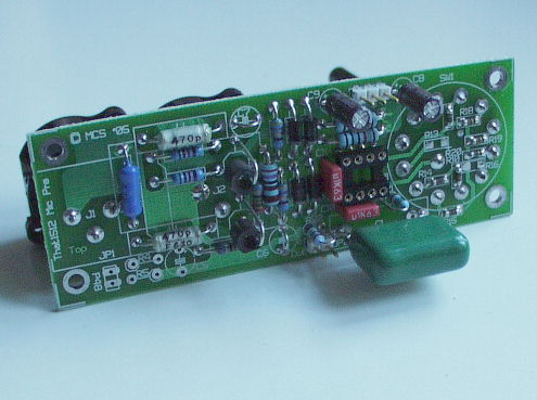
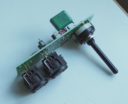
I finally received the boards so I could get the thing built. And it works...

Here's a couple of photos:

ThatMic-comp-photo.495_400.jpg


ThatMic-top-photo.495_400.jpg


I built two of them. One has a "noisy" switch. When I set the preamp to a high gain setting (50dB+), I get a lot of noise by pushing/flexing the switch shaft. The other switch is completely quiet. Has anybody seen this behaviour before? They are standard Lorlins, if somebody doesn't recognise them from the photos.

Best regards,

Mikkel C. Simonsen
 
I'm just guessing, but seeing as you don't use a DC blocking cap on the gain control, maybe the THAT chip on the noisy channel produces a higher DC offset than the other. You could try swapping the chips to verify it really is the switch that is noisy.
 
I remember seeing somewhere a note saying if you ground one of the inputs you can treat the remaining input as mono. Am I thinking of a different single-chip mic pre?
Also, the THATdn138 document which talks about figureing out gain for the THAT15* chips talk about putting a 6800u cap in series with the gain control to avoid "changes in dc
output offset with gain." Has anyone had problems with this?
 
Thanks for the clearification. Yeah, I meant unbalanced input. I was on a borrowed computer, and didn't make put things quite right.
The THAT note I mentioned can be found here: www.thatcorp.com/datashts/dn138.pdf

mediatechnology, if you could post the servo suggestions that'd be kind of you. I don't understand what you're describing, and I think I'm useing the wrong search terms to find documents on utilizing servos.

Thanks everyone
 
Seventh Circle just came out with a THAT 1512/1646 based mic pre. Schematics are available on the SCA web page. I ordered two, couldn't resist for the price.

T15 pre

-Chris
 
Ouch....just made it more difficult to make a decision: MCS is making a Kit for 35 Euros, Owel has his kit at 99 us and then Seventh Circle has it's own at 75..... Everyone using THAT 15XX series....interesting.....

Wayne any advice??
 
I include the schematic in the package for my preamp. I just don't have it posted online.

On my pre, I have an output servo after the THAT chip to eliminate coupling caps before going to the 1646....

I use a capacitor for the Rgain leg in conjunction with the selector switch for gain selection.

All the capacitor does is reduce/eliminate the clicking when selecting gain via the selector switches.... so you don't get a popping sound.

If you used a potentiometer for Rg (and I have solder pads on the PCB for that option), giving you a continuous gain level control, you don't need this capacitor.

As for the "input servo", it's not really to reduce the value of the input coupling caps. It's an "Rgain servo", serves the same function as the capacitorabove in the Rgain leg... i.e. to reduce/eliminate clicking when rotating the gain selector switch.

Here's a recording a friend made using only SC-1 on all instruments. (Unmastered version) in case you're interested to hear how the SC-1 sounds.

http://www.fivefishstudios.com/audio/SC-1PreampDemo.mp3
Recording setup details can be found here. www.fivefishstudios.com/audio
 
By the way good job on your preamp Owel. Nice layout too. The assembly instructions you provide are fantastic.

Hey thanks! The instructions have been newbie tested several times. :)

I wish there's a simple way to totally eliminate that input coupling cap. But with 48V in that vicinity, caps are a must required. (Maybe use an input trafo instead?)

I think regardless of the value of that input cap, high or low, input clamping protection is more important to protect against discharges by the same capacitor. Otherwise, we'll have a fried chip.
 
I decided to "cheat" a little and move the rails around to fit the DC potential of the mic. It does work and is fry-proof.

That's inGenius! (tm) Great stuff.

Thanks for the offer (re: AES paper). I think I have the papers somewhere... probably buried under my Digikey, Mouser, and Allied catalogs. I need to look for it.
 

Latest posts

Back
Top