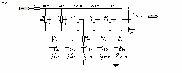
The math behind this EQ circuit using inductors.

GroupDIY Audio Forum

Help Support GroupDIY Audio Forum:

This site may earn a commission from merchant affiliate links, including eBay, Amazon, and others.

Analog_Fan

Well-known member
Joined
Mar 22, 2022
Messages
570
Location
Universe
th-2608662418.jpeg

Hi there,

Some 2 years ago, i saw / found a EQ guitar pedal circuit.
I did a new search and found the upper circuit with is pretty similar.

Back than, i bought the correct inductors, but they where SMD and pretty small to handle when i got them and the project didn't get build.
But i do like this circuit due to low part count.

This circuit might contain parts values that are not standard.
What's the math behind these parts in series?

680 Ohm + capacitor + inductor and the 1K pot (cut / boost).

Te be able to select other bands.
 
The freq for each band is f=1/(2pi sqrt(L*C) )
A alternate way:
f = sqrt(0.02533/L^2 * C^2)
where 0.02533 is ~=1/(4pi^2)
In other words it combines the constants and simplifies calculator entry... more or less.
 
Hi i m working at somenthing similar... But no inductors... Found the attached schemo on a site for tube gears.
Not so Expert but i think the concept Is to create a bandpass for each section...
So how Wide Is the broadband, Q, in your design?
Best
 

Attachments

  • Voltage Divider and Six-Band Equalizer Values.png
    Voltage Divider and Six-Band Equalizer Values.png
    46.2 KB
The equations for the frequency & bandwidth are given here: RLC circuit - Wikipedia

If you have Python handy:
Python:
>>> from math import *
>>> L = 1.0
>>> C = 6.8e-6
>>> 1/(2.0*pi*sqrt(L*C))
61.03313457673969


The other relevant information is that the second (right-hand) OP-270E forms a non-inverting amplifier (see Operational amplifier applications - Wikipedia) whose gain depends on the ratio of R13 to the impedance between the -ve input and ground.

The impedance of R3/C2/L1 (etc.) will reach a minimum at the resonant frequency so will produce a boost in the frequency response at that point. How big the boost is depends on R3+R4 (etc.). Smaller values of R3+R4 give a bigger boost. (The circuit doesn't appear to offer any ability to cut frequency bands).
 
@richiyobs do you have a link to that TubeCad page please?

Cheers

Ian

Here It Is
https://www.tubecad.com/2020/08/blog0510.htm
Is It possibile to implement this approach to your passive eq?
If so can you please explain how to add middle band without inductor?
I tried but no good results... Even with opamp gyrator i was not able... I only get alteration and interference respect to your original design
Thanks for your attention
Best
 
Last edited:
The equations for the frequency & bandwidth are given here: RLC circuit - Wikipedia

If you have Python handy:
Python:
>>> from math import *
>>> L = 1.0
>>> C = 6.8e-6
>>> 1/(2.0*pi*sqrt(L*C))
61.03313457673969


The other relevant information is that the second (right-hand) OP-270E forms a non-inverting amplifier (see Operational amplifier applications - Wikipedia) whose gain depends on the ratio of R13 to the impedance between the -ve input and ground.

The impedance of R3/C2/L1 (etc.) will reach a minimum at the resonant frequency so will produce a boost in the frequency response at that point. How big the boost is depends on R3+R4 (etc.). Smaller values of R3+R4 give a bigger boost. (The circuit doesn't appear to offer any ability to cut frequency bands).
Thnx

Somewhat i get the same number, but 1000 times smaller.
0.0610331346

using: double test = 1/(2.0 * M_PI * std::sqrt(inductor * capacitor));

i use 3 QLineedit's and the simple numbers: 6.8 (uF) without the "e-6"
double capacitor = ui->lineEdit_capacitor->text().toDouble();
double inductor = ui->lineEdit_inductor->text().toDouble();

This circuit is found in some guitar pedal, iBanez or so.
So someone broke his mind over it, don't know the effect of it.
But the low part count is attractive.
 
The freq for each band is f=1/(2pi sqrt(L*C) )
A alternate way:
f = sqrt(0.02533/L^2 * C^2)
where 0.02533 is ~=1/(4pi^2)
In other words it combines the constants and simplifies calculator entry... more or less.
RCL - formula.jpeg


double capacitor = ui->lineEdit_capacitor->text().toDouble();
QDebug debug=qDebug();
debug << "My floating point Number is: " << capacitor << endl;

double inductor = ui->lineEdit_inductor->text().toDouble();

//double test = 1/(2.0 * M_PI * std::sqrt(inductor * capacitor));
double test = std::sqrt(0.02533 / inductor^2 * capacitor^2);

This "^2"?
 
View attachment 114125


double capacitor = ui->lineEdit_capacitor->text().toDouble();
QDebug debug=qDebug();
debug << "My floating point Number is: " << capacitor << endl;

double inductor = ui->lineEdit_inductor->text().toDouble();

//double test = 1/(2.0 * M_PI * std::sqrt(inductor * capacitor));
double test = std::sqrt(0.02533 / inductor^2 * capacitor^2);

This "^2"?
I think it may not parse correctly without the extra parentheses around L^2*C^2.
It might be incorrectly read as (0.02533 / L^2) * C^2
using math rules of precedence.
 
(The circuit doesn't appear to offer any ability to cut frequency bands).
This topology offers boost and cut:

eq-f8.gif
 
I think it may not parse correctly without the extra parentheses around L^2*C^2.
It might be incorrectly read as (0.02533 / L^2) * C^2
using math rules of precedence.


https://en.cppreference.com/w/cpp/language/operator_arithmetic
bitwise XOR a ^ b T operator^(const T &a, const T2 &b);

It can't handle "double values"


https://en.wikipedia.org/wiki/RLC_circuitRLC - WIKI formula.jpeg

I'm looking at band pass filter, correct?

There are some calculators here:
https://electronicbase.net/band-pass-filter-calculator/
This is the formula of the upper: https://web.archive.org/web/20070701185307/https://www.opamplabs.com/cfl.htm
double test = 159.154/std::sqrt(inductor * capacitor);
(works)


https://electronicbase.net/band-pass-filter-calculator/RLC -- Formula.jpeg

double test = 1/(2.0 * M_PI * std::sqrt(inductor * capacitor));

returns a number that's 1000 x smaller that the above formula.


The wiki formula (from above):
double test = 1/(std::sqrt(inductor * capacitor));
returns a number not even close.
 
Here It Is
https://www.tubecad.com/2020/08/blog0510.htm
Is It possibile to implement this approach to your passive eq?
If so can you please explain how to add middle band without inductor?
I tried but no good results... Even with opamp gyrator i was not able... I only get alteration and interference respect to your original design
Thanks for your attention
Best
The reason I asked for the link to the TubeCad page is because his single resistor ladder technique is an almost exact copy of my own passive mastering EQ. The TubeCad post is dated 14th August 202 but I published my design back in April 2017. The main difference between his EQ and mine is that mine is 100% passive and the TubeCad one is active and will only work with a balanced input signal.

With the passive EQ I think there is no option but to use an inductor but I will look into it because inductors are very expensive. One possibility is to use a bridged T notch filter instead of the inductor. Unfortunately the notch filter has a high impedance at the resonance but we need a low impedance.

Cheers

ian
 
because inductors are very expensive.

I wanna buy a roll of 1mm² copper wire, they sell it per KG, seam to be about 145 meters, but i looked at ferret inductor cores in a "hobby" shop, there are many sizes, thicknesses, diameters, etc and you're clueless again.

Anyone knows the formulas how to make them? how to choose the diameter of the ferret core, etc, etc.
Would be cool to learn, so i can make a calculator in QT.

if you need to buy only one or 2 value, mouser has a minimum of 50€ lower limit.
Making them yourselfs seems the best option.
 
Back
Top