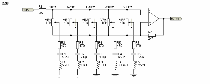
So if I'm thinking about this correctly:
1) The pot(s) are across the input terminals, which means they are in parallel with the differential input resistance of the op-amp. Assuming the input signal magnitude allows the op-amp to do it's thing, it will keep the differential voltage across the pot at zero, meaning no current through the pot. Hence it shouldn't factor into the gain equation at either extreme.
2) With the pot dialed fully 'up', the circuit looks like a divider between R1 and the tone network, and the op-amp looks like a unity gain buffer. At (maximum) cut, and at the resonant frequency, the C and L cancel, meaning the gain (reduction) at that frequency will be (looking at the first band): R2/(R2+R1), or with the values listed, approximately 17dB reduction. So at each resonant frequency, the gain reduction is set by R1, and the series resistance(s) R2 through R6.
3) With the pot dialed fully 'down', the circuit looks like a regular non-inverting amplifier, with gain set by R7 and R2, or with the values listed, a gain of 16.5 (or again, roughly 17dB of boost).
Not sure how to think about it in the middle: since the feedback cancels the voltage across the pot, there can be no current into the pot, hence no voltage developed across the RLC network. One way to think about it as two identical networks: one providing the attenuation function of #2 above, with an identical network providing gain. As the pot is dialed lower, attenuation decreases as gain is increasing, and in the middle, they cancel, meaning unity gain through the pass band.


