The official G9 help thread

GroupDIY Audio Forum

Help Support GroupDIY Audio Forum:

This site may earn a commission from merchant affiliate links, including eBay, Amazon, and others.
Ok, so no one is interested in G9 grounding. Well, other than the fact that I have the inputs in the wrong order on the board, I've determined that it is correct.

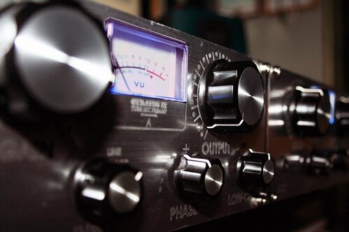
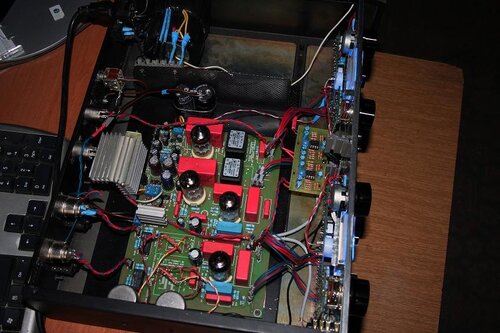
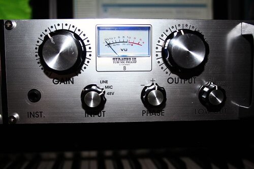
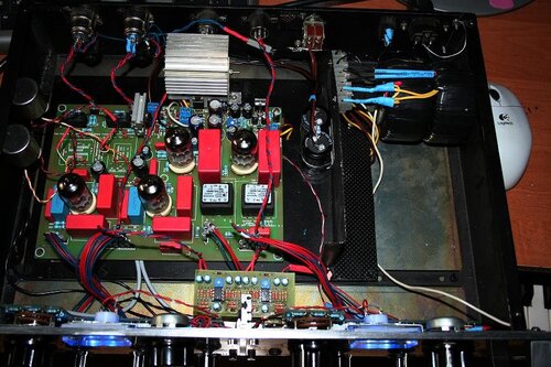
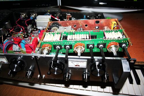
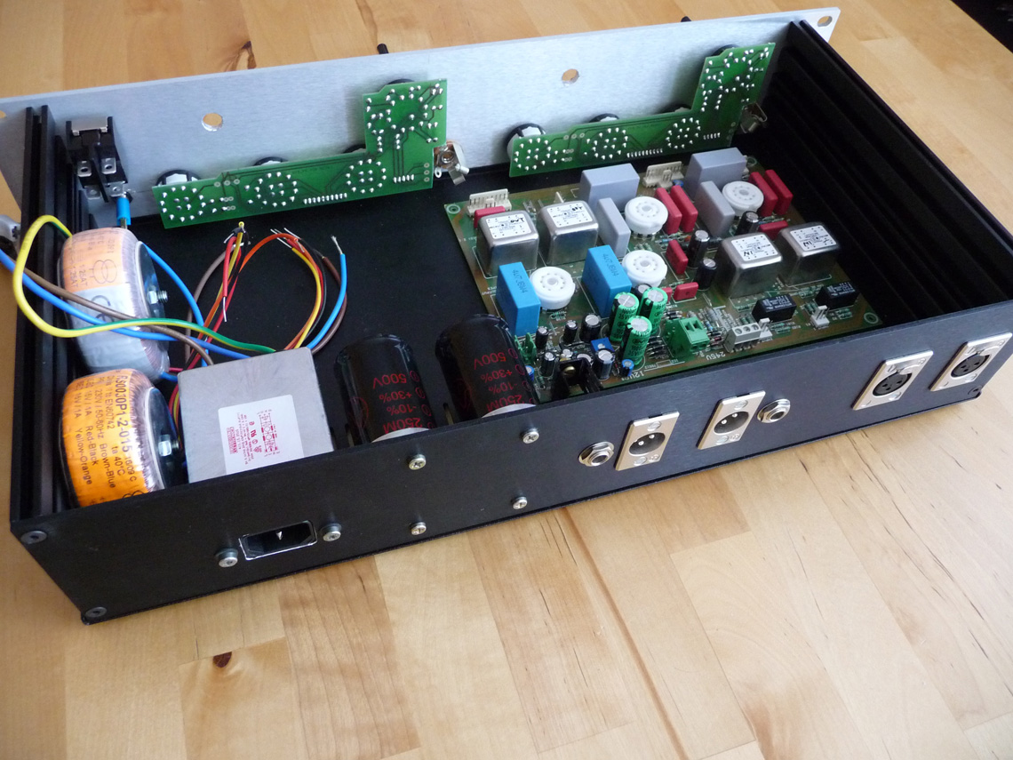
And other than putting in the tubes and getting a freaking fuse, I'm ready to turn this sucker on and hope for no sparks. Anyway, here are some pics.

http://fucanay.fischerworks.com/diy/G9/G9_1.jpg
http://fucanay.fischerworks.com/diy/G9/G9_2.jpg
http://fucanay.fischerworks.com/diy/G9/G9_3.jpg
http://fucanay.fischerworks.com/diy/G9/G9_4.jpg

I'll fix the diagram and leave it up once I've confirmed it works. well.

Matt

 
> the little solder tab on the same XLR  ... wire the Mains ground on the IEC to this point also

Uh, not really.

Wall-power ground goes directly to chassis, shortest way, dedicated bonding point.
vwy1pt.gif


Look inside any Bee-ringer, PC power supply, etc. The IEC ground goes to a chassis stud a few inches away, and nothing else (maybe other chassis bonds) lands here.
303iec.jpg


What you done will work. In fact I might not fix it. But in some moderately unlikely but possible situations, there may be a Safety Hazard.

As an unlikely case: if a fully-live 120V HOT wire hit the mike jack, the 200++Amp fault current could blow-up the mikejack lugs and mike cable, leaving the chassis fully hot.

What to do with pin 1 is controversial. Partly because many variations work most of the time. Since your PCB clearly expects pin 1 to arrive at the PCB, the way you did it (one pin-1 tied to nearest chassis lug) seems logical, and won't give trouble except in severe cases of interference or ground-loop, situations that small studios rarely run into.
 
Thanks PRR. I'm really trying to do everything right before I flip this thing on. The reason I did it the way I did was because Gyraf's site says:

- Connect 0V/Gnd to chassis at one - and only one - point: At the input XLR's.

- Connect the power ground from the power inlet to the ground at the input XLS's also.

I interpreted this as I have it drawn there. Now if this is not right, then I not only don't mind changing it, I'd be happy to. I am terrible at wiring and this is the best job I've done yet. So I want it to all be right, and neat. This is my first tube anything and I'm kind of afraid of it, especially the big caps. So the less messing around with it after power on the better.

Matt
 
fucanay,

in my G9 build, which has zero pin1 problem and no pin1 related hum obviously, I connected it like this image from PRR:

303iec.jpg


Then connect one of the XLR input pin1 to that point in chassis also.


I have now used the same idea with another p2p two channel tube preamp and it works there as well. But in there due to very different p2p grounding layout, I connected both XLR input pin1 to that same chassis point.

[edit]


The above scheme isn't the only one, but the IEC connector chassis point always applies. In order to understand some of the rules on ground loops and current flow, there have been many threads in the past, but here is a more recent one with several quite enlightened points made.

http://www.groupdiy.com/index.php?topic=33819.0
 
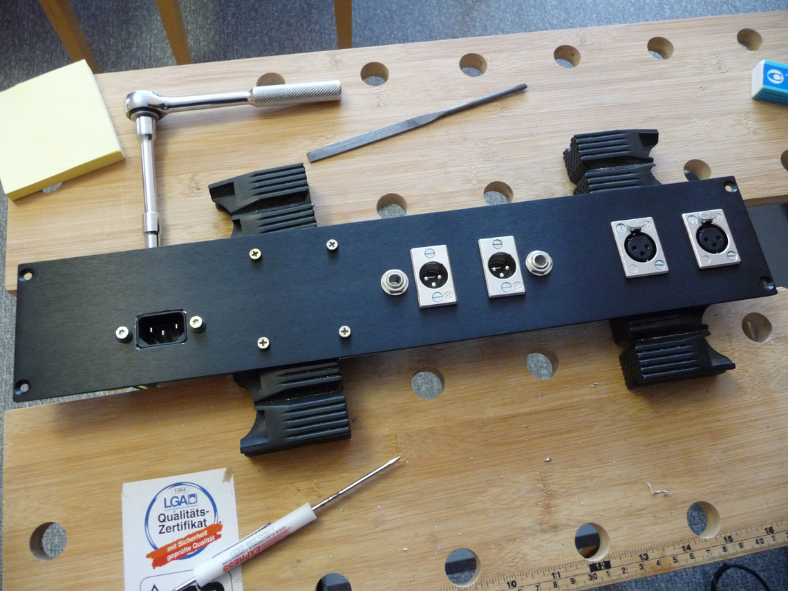
Ok, so I will have two ground points. One for the mains ground, close to IEC jack. And one for the XLR pin 1 where it just bridges to the little solder tab on the shell of the XLR and therefor connects to the chassis. That should cover it. I see what PRR was talking about in terms of safety, so I see this as the best way to do it now.

On another topic, am I right that I should be using a 1 amp slow blow fuse on this thing? I am real close to firing this thing up and getting pretty excited about it. Probably early next week.

Matt
 
How bright are the tubes supposed to be when powered on? Even in the dark they are pretty dim. I have all the right voltages. I haven't actually tried any audio tests, so maybe I'm just worrying for no reason. Guess I'll go plug it in.

Matt
 
I guess I'm all done. Sounds amazing. No hum, no oscillation. Just pure wonderful sound.

Jakob,you are the man. Thanks to all who asked questions and figured out problems before I even started.

Matt
 
I have had only one actual problem on this whole build. The phase switch on channel 1 doesn't work right. In the "In" position, it doesn't do anything, but it works in the "Out" position. I haven't looked into it yet. but this part of the circuit is super simple, so it should be a quick fix.

I brought this thing to our rehearsal space last night and had my singer sing through it and it was amazing. Next time I'm going to feed it into some Pico compressors and it should be our go to vocal pre from now on. Still need to try it on snare and kick drums, but I love this thing so far. Much more than the fetboys I built.

Matt
 
fucanay said:
I have had only one actual problem on this whole build. The phase switch on channel 1 doesn't work right. In the "In" position, it doesn't do anything, but it works in the "Out" position.

I haven't built a G9 yet but it sounds like you could have your phase switch wired up backwards. Or maybe its an OFF-ON switch instead of ON-OFF? dunno.
 
I don't think it's possible to really put this thing in backwards, or at least I recall reading that. My guess, without having investigated it, is that I either have the Lorlin stop set wrong or I have a bad connection somewhere. I'll have it back open in a few days and see which it is. Either way, it should be a really easy fix.

Matt
 
fucanay said:
Ok, so no one is interested in G9 grounding. Well, other than the fact that I have the inputs in the wrong order on the board, I've determined that it is correct.

;D Il really interested because i check the "best" method to do this with my Gyraf. I need to read the "point to point post"  :)

g9_grounding.gif

I think your color wiring is not the good one. Maybe i am wrong. Input in PCB is left to right : IN-,IN+,GND

XLR
1 Chassis ground (cable shield)
2 positive polarity terminal ("hot")
3 return terminal[2] ("cold")

123.jpg


... Can't wait to finish it  :-X
 
You are totally right. I need to fix that graphic all around.  I haven't revisited it because it all worked with now hum or oscilation on first power up. I'll try to do the final version soon.

Matt
 
Just to be sure, no way to use a input instrument stereo switchcraft for the oscillation Mod ?

switchcraft_jack_1_4_stereo_b29644.jpg


120.jpg

Other query is about jack output. I see a lot of standard cable ( XLR to jack ) with ground and - together. Do i need to add a switch to do this and select if i need to connect theses wiring to use jack ? I have no idea about this...
Thanks
 
Hey guys...Having a tough time with rotary switches here. Anyone have a part number available from Digikey or Allied or any other distributer? Thanks.
 
Hi guys!

I'm having problems with power transformers. When they're connected, the first one (220V from the mains) runs very hot, and g9 doesn't turn on.

This are my transformers.

http://picasaweb.google.si/lh/photo/uwhU56v35SUBTYX4wjLK1A?authkey=Gv1sRgCNjc_I2Z1oDtvQE&feat=directlink
http://picasaweb.google.si/lh/photo/lH6EHiE767gR_nlkrIizww?authkey=Gv1sRgCNjc_I2Z1oDtvQE&feat=directlink

trasnlation of marks on toroid picture:

Prim: Črna-Black

Sec: Rdeča-Red
      Bela-White (it was white and conected together, then i took off white isolation and stripped the wires, so now they are raw copper (laquered)


I connected them (trafos itself) to 220V, and this is what i get:

15V on 3&4
15V on 5&6

There is no voltage between 3&5 or 4&6

If i get it all right, then (in my case) 3&6 and 4&5 of T2 must be connected togetger and they run to 15V connector (3&6 to one pin, and 4&5 to another) when there is also connection from one of secundars of T1? When i did that, i get some sort of shortage, and transformer got very hot.
 
Janou said:
Other query is about jack output. I see a lot of standard cable ( XLR to jack ) with ground and - together. Do i need to add a switch to do this and select if i need to connect theses wiring to use jack ? I have no idea about this...

Do you want an unbalanced output? If so, just use a mono jack socket with cold tied to ground. If you want balanced, use a stereo jack socket. If you want both, use a stereo jack socket, and when you want it to be unbalanced, use a mono (TS) jack in the socket at the G9 to cause the cold to be shorted to ground.
 
Forget about my previus post. It's working! I was watching audiophreak's trafo wiring picture, and it's wrong! I hook'd it another way and it's working. There is connection between those secundars leads which in normal mode doesn't produce 15v.
But i have another question. How much must tubes glow? I thaught they will glow like christmas tree, but they produce very little ammount of light. (pics later)
And another thing: Can someone please give me a summary of voltage measure points (and maybe advisable values) . Everywhere i read, there is always written: "measure voltage here, measure voltage there"), but where is other (minus) point of measuring? Ground?

Thanx, and greetings.
 
gregcs1 said:
How much must tubes glow? I thaught they will glow like christmas tree, but they produce very little ammount of light. (pics later)

The heater glow is just a mellow kind of orange light.  It's not bright like a Christmas tree. 


Yes.  All voltage measurements are in relation to ground unless you're measuring something like voltage drop across a resistor.  What you're looking for, though, is voltage between the test point and ground.

Cheers,
--
Don
 

Latest posts

Back
Top