The official G9 help thread

GroupDIY Audio Forum

Help Support GroupDIY Audio Forum:

This site may earn a commission from merchant affiliate links, including eBay, Amazon, and others.
I think your problem is that the HT voltage is not high enough to make the TL783 regulate.
You will likely need to replace the 2nd(=stepup) transformer to something like 2x12V .
That should make your HT voltage higher so the TL783 can regulate..

220uF is cool :thumb:

Lars
 
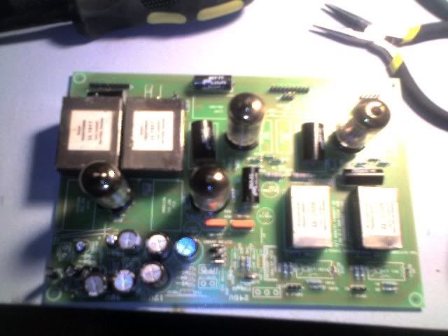
Getting there, just a few more components and the interconnects!

img009.jpg
 
[quote author="Black Dog"]I think your problem is that the HT voltage is not high enough to make the TL783 regulate.
You will likely need to replace the 2nd(=stepup) transformer to something like 2x12V .
That should make your HT voltage higher so the TL783 can regulate..

220uF is cool :thumb:

Lars[/quote]

Got my new 2X12 tranny today and it works like a charm.
311V before and 246V after the regulator.
Still some hum I've got to sort out.
We are getting there slowly :grin:
 
Ok, heater voltage is ok now but I still got some 100Hz hum (with both in and output on lowest setting ).
I have a ripple of 1,7 mV on both the 12V and the 245V heater.
I even upped the (c14 and c15) caps from 220 to 330uF but that did not make any difference.

Is it normall to have a small amount of hum in a OK working G9?
 
[quote author="radiance"]
Is it normall to have a small amount of hum in a OK working G9?[/quote]

Small amount beeing -85,00 dB.

I just connected the G9 to the in's and out's from my audio interface and read the meters in Logic (DAW). I guess it's not very acurate... :?
 
hello everybody,
i've read through the G9 threads on the meta, but still need some help on this one. i'm really close to finishing my G9 build, but i've run into a problem.
i was able to rid my oscillation on the higher gain settings with axel's oscillation fix (thanks for that one axel! :thumb: ).
i'm getting good gain out of both channels and all front panel controls work properly. i'm getting my "click-ity-click" from my relays when switching "line" on/off. both mic and DI sound very good so far, but...
i have 48V PP on both pin 2 and 3 of both channel input XLRs at the main board input jumpers. I've checked for shorts and cannot find any on both main and control pcbs, nor any shorts in my wiring (XLR in, 10-pin, 5-pin, etc). Without control boards and XLRs connected to main board I still get 48V on both pins 2 & 3 on the main board input jumpers (so the problem has to be on the main board).
I'm at a loss after about 3 hours of looking at schems, pcb traces and pads. :? Why would I get PP on both pins?
Any suggestions or help would be greatly appreciated.
thanks
-grant
 
I'm not sure what your problem is - you should have 48V phantom at input XLRs pins 2+3 - when phantom power is engaged.

Phantom power is switched by the input selector - look at the layout .PDF's on the G9 webpage - it switches from the "from 48V" to the "P48" points on each channel.

Use an ohmmeter to verify switching and connection/disconnection from phantom supply.

Jakob E.
 
hi jakob,
thank you for the info.
i looked at all the information on the G9 page at your site before, during and after my build and did notice that both pins 2 & 3 are connected to PP.
my connection/disconnect via 48V/mic/line switch does turn on and off the PP
as verified with my DMM.
the reason i thought something might be wrong initially was that when i connected a condensor mic to the mic input there was a voltage drop after a minute or two from 48V to about 39V. this seemed strange and i thought possibly that there was something wrong in my PP circuit. i'm using a TIP 122 (instead of the 121) for regulation. i'll have to do more tests to see if i can find anything i might have done wrong and overlooked.
thanks for your help. very much appreciated.
regards,
grant
 
Having used my g9 for I couple of weeks now I have to say that it sound wonderfull.
When I use it on an insert of my mix bus I notice a slight low end roll off, in other words, it's lacking some bottom end. When using it as a mic pre I had not noticed this though.
Is this normall? I have no good way of meassuring this but I do hear it.

A wild guess....Could I've mixed up the in and output transformers? (I'm using Oep's), or would that have been way more obvious than a slight lack of bottom end? I mean, the unit is working as it should (low cut works fine..).

Ok, and if I did wire the trannies right, where should I be looking first?

Also, I'm using rather thin microphone (2 wires and a shield) cable to and from the XLR's (and to the frontpanel jack). Could it have something to do with that?

Thanks and Merry Christmas to whoever reads it at this time.....
 
Ok, I did some meassurments and although they're not really acurate I think they will give an idea of the lack of low-end I'm talking about.

G9 inserted

Hz____dB
10___-14,3
16___-10,2
21___-7,3
26___-5,5
32___-4,4
37___-4,0
43___-3,8
48___-3,5
53___-4,3
59___-3,5
64___-4,8
69___-4,4

G9 Bypassed
Hz_____dB
10___-2,5
16___-2,4
21___-2,5
26___-2,4
32___-2,6
37___-2,5
43___-2,6
48___-2,6
53___-3,7
59___-2,8
64___-4,2
69___-4,4

It's all done with a sine sweep recorded through the G9 into my DAW...
Maybe it's just the frequentie characteristics of the Oep transformers I've used.
 
Hi,

I got the board of G9 and start to collecting parts for the project.

I wonder if anyone chassis-mount the pots and switches rather than using the PCB? If I do it in this way should all the componet on the control pcb be directly soldered on the swtiches/pot? I am asking because when I built guitar amp some componet should be as close as possible to avoid oscillation.
Also I am thinking to use pots or 24-stepped attenuator to replace the 12-position switch so that I can have more control on gain. What do u think?


laiben
 
hi laiben,
i do not think you'll gain anything by not mounting the switches to the control pcb directly. flying leads to all those switches seems like it's more trouble than it's worth. jakob has a very well thought out control pcb layout.

the oscillation problems that occur in some of the G9 builds (including mine) are due to the rather long traces from the DI jack to the input xfrmr and related cap (C2 and C102) or lack of shielding on the in/out xfrmrs. look in the G9 meta for the oscillation fix thread.

as for a 24 position gain switch, the G9 does have an output trim pot which allows for various levels of gain control even with the 12 position switch. once again, i'm not sure you'll gain anything from trying to apply a 24 position switch, but this is DIY and you're welcome to try.
regards,
grant
 
Thanks dissonantstring. I think i will just follow the PCB strictly for the first build. I will report to all of you if I did any other mod to G9. Yeah right this is a DIY! But you know... we have too many projects and too much things to try and too little time!
 
Another Power Transformer question...

If I use 50VA transformer instead of 30VA transformer, what that generate much more heat? I am asking because I always feel that more 'headroom' is safer. Also look at the guts of those Hi-end audiophile equipment their transformer are always ridiculously big!


laiben
 

Latest posts

Back
Top