supply voltages. signal-through..
You are using an out of date browser. It may not display this or other websites correctly.
You should upgrade or use an alternative browser.
You should upgrade or use an alternative browser.
The official G9 help thread
- Thread starter gyraf
- Start date


Help Support GroupDIY Audio Forum:
This site may earn a commission from merchant affiliate
links, including eBay, Amazon, and others.
I am building the G9 and all the wiring is done. My B+ without tube is 285VDC (the schematic said 245V), is that too high? I am using two 330uF/450V cap instead of the suggested 100uf cap in the schematic, will it cause any problem?
Thanks
laiben
Thanks
laiben
maxime
Well-known member
the caps size won't affect the tension value up to that point. I think you should try to measure tension before and after the regulator to see if it's properly working. are your filaments glowing ? if not the problem may be a overheating 12 volts regulator (78s12)... this one really needs sufficient cooling.
the 783 needs current passing through it to start regulating. if the filament don't warm the cathode, no current through the tube...
maxime
the 783 needs current passing through it to start regulating. if the filament don't warm the cathode, no current through the tube...
maxime
[quote author="maxime"]the caps size won't affect the tension value up to that point. I think you should try to measure tension before and after the regulator to see if it's properly working. are your filaments glowing ? if not the problem may be a overheating 12 volts regulator (78s12)... this one really needs sufficient cooling.
the 783 needs current passing through it to start regulating. if the filament don't warm the cathode, no current through the tube...
maxime[/quote]
Thanks for the reply maxime. I measure the 285V at the 1K/2W resistor (R31 if I remember correctly), without tubes.
I already have a big heatsink with the 78S12, I will post a picture when I back home.
I will also report all the voltage in and out of each regulator. Thanks!
laiben
maxime
Well-known member
without tubes, the regulator (because no current flows through it) won't bring your high tension (285V) to a lower 240V regulated output.
put your tubes on the board for testing :green:
best regards
maxime
put your tubes on the board for testing :green:
best regards
maxime


![Soldering Iron Kit, 120W LED Digital Advanced Solder Iron Soldering Gun kit, 110V Welding Tools, Smart Temperature Control [356℉-932℉], Extra 5pcs Tips, Auto Sleep, Temp Calibration, Orange](https://m.media-amazon.com/images/I/51sFKu9SdeL._SL500_.jpg)


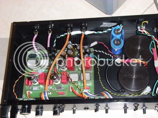
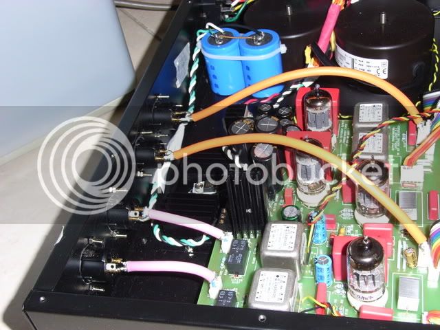
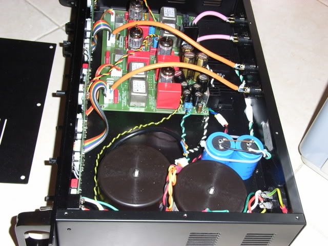
well I just finished my G9, and it hums :sad:
Here is the clip of the hum when there is no input, turning the gain knob will not make the hum loud, turning the output knob will increase the hum.
http://www.mediamax.com/laiben/Hosted/G9%20hum.mp3
chopstick makes no difference, any suggestion?
some pics:
laiben
Here is the clip of the hum when there is no input, turning the gain knob will not make the hum loud, turning the output knob will increase the hum.
http://www.mediamax.com/laiben/Hosted/G9%20hum.mp3
chopstick makes no difference, any suggestion?
some pics:
laiben
ChrioN
Well-known member
chopsticks? Try moving the wires and transformers around a bit.
jdr
Active member
From the pictures, it looks like you haven't put your star ground at the input XLRs. From gyraf's g9 diy page:
"- Connect 0V/Gnd to chassis at one - and only one - point: At the input XLR's.
- Connect the power ground from the power inlet to the ground at the input XLR's also."
Also, on the same page, Jakob recommends keeping the power transformer far away from the front panel because " the 'output gain' is somewhat highohmic and hence sensitive"
Hope that helps. Good Luck!
John
Thanks JDR!! I can't believe I read all the meta but forget to look at Jakob's page!! Now I connect the pin1 of the one of the XLR to the chassis and now the G9 is slient as hell!
Now the channel 1 is good, but the channel 2 is very quiet :evil: No gain at all. Swapping tubes did no help, I am gonna check the wiring but if you have an idea please give me some insight.
laiben
[quote author="jdr"]From the pictures, it looks like you haven't put your star ground at the input XLRs. From gyraf's g9 diy page:
"- Connect 0V/Gnd to chassis at one - and only one - point: At the input XLR's.
- Connect the power ground from the power inlet to the ground at the input XLR's also."
Also, on the same page, Jakob recommends keeping the power transformer far away from the front panel because " the 'output gain' is somewhat highohmic and hence sensitive"
Hope that helps. Good Luck!
John[/quote]
ubxf
Well-known member
After dealing with oscilation and cutting the traces and connecting directly
with shielded wire. The result is that the first instrument input is dead quiet
the second one does'nt oscilate any more but has a hum, btw that same channel is quiet thru the microphone input. Any help would be greatly appreciated.
francois
with shielded wire. The result is that the first instrument input is dead quiet
the second one does'nt oscilate any more but has a hum, btw that same channel is quiet thru the microphone input. Any help would be greatly appreciated.
francois
Try with a electrostatic shield (a grounded metal plate or foil of some kind) between the transformers and the pcb/frontpanel-pcb..
Jakob E.
Jakob E.
AudioJunkie
Well-known member
Before I try and power up my G9 on Saturday, I had a couple questions about wiring the power transformers. Just want to be sure before I do anything to blow up this expensive project.
1: I'm using Amveco's. But the diagram only tells which Primary wire is 0 and which is 115V.
0 - Yellow ====== Green
|
110 - Black ====== Red
0 - Red ====== Brown
|
110 - Violet ====== Blue
So is Brown and Green on the secondaries the Ov and Red/Blue the 15V?
2: Assuming I have that part right. Here's how I have them wired now.
1st transformer:
IEC + to Black/Violet
IEC - to Red/Yellow
Red and Green will go to 15V/1Amp next to the 280 jack.
Blue and Brown will go to 15V on the right of the board and Trans. 2
Then coming off of the Blue and Brown from Trans 1, Trans. 2 will be Green/Brown to the Ov Brown and Red/Blue to the 15V Blue?
Then Black/Red combined and Yellow will be Ov and Violet will be 220V or whatever?
3: And finally when hooking to the board. Which of each pairs is the Ov and which is other?
Hope this makes sense.
Daniel
madreza
Well-known member
Hi
My G9 still doesn't work
after spending some time fixing it , I'm here to ask for HELP.
Tubes don't light up. At first I thought it was the HT
checked the HT and I get 300 V :shock:
after a while I noticed that the 12V LED doesn't light up either
then I came to check the 12V, and even changed the regulator
didn't work
I have 230V, 17V and 300V HT
I don't have anything between the pin 2 ( Ground )of the regulator and pin 1 or 3
any ideas ?
THX
Check that you get a correct DC voltage to the input of the 78S12 heater-regulator - you should at least have some 14-15V DC here. If you don't, check why - look at the schematic and follow the layout. some AC>rectifier>electrolytics>regulator. not complicated at all.
If you have DC at the input, but not at the output, of the 78S12, look for stuff shorting the heater supplies somewhere on the PCB.
As it has been mentioned several times in this thread before, the HT will be high until the tubes have heated - which they won't if the 12V is missing..
Take care - when heaters are down, there's nothing to discharge the HT voltage!!
Jakob E.
madreza
Well-known member
Great and Fast as Usual :razz:
Thanks Jakob
:sam: :sam: :sam:
Thanks Jakob
:sam: :sam: :sam:
madreza
Well-known member
Hi , me again ! :grin:
Solved my problem ! It was a bad soldered point !
Now, I have 226V and 211 V on the HT
I used 2 2*15V Txformer. I saw on your schematic that I should use 1 2*15 and 1 2*12 V !!!!
Can this help rising the HT ? ( I guess so, you'd get more than 230 AC )
what about rising the values of R34 and R35+36 ?
( Ok, I guess I have the answer to my question : it won't help because TL783 doesn't have enough voltage to regulate !? )
Can this help rising the HT ?
yes, that is the idea.
[quote author="madreza"]Hi , me again ! :grin:
Solved my problem ! It was a bad soldered point !
Now, I have 226V and 211 V on the HT
I used 2 2*15V Txformer. I saw on your schematic that I should use 1 2*15 and 1 2*12 V !!!!
Can this help rising the HT ? ( I guess so, you'd get more than 230 AC )
what about rising the values of R34 and R35+36 ?
( Ok, I guess I have the answer to my question : it won't help because TL783 doesn't have enough voltage to regulate !? )[/quote]Some good stuff here on getting the HT right:
http://www.groupdiy.com/index.php?topic=11347
Cheers
Nick
nashkato
Well-known member
sorry  i posted this question in the lab too,until i saw this official thread for the g9,
i´m gonna delete it there.
on the pcb is a value of 220n given for C3 and C103.
in the parts list with 470n
whats the right one.?
thanx in advance.
i posted this question in the lab too,until i saw this official thread for the g9,i´m gonna delete it there.
on the pcb is a value of 220n given for C3 and C103.
in the parts list with 470n
whats the right one.?
thanx in advance.
Similar threads
- Replies
- 6
- Views
- 1K
- Replies
- 1
- Views
- 1K
- Replies
- 3
- Views
- 1K