The official G9 help thread

GroupDIY Audio Forum

Help Support GroupDIY Audio Forum:

This site may earn a commission from merchant affiliate links, including eBay, Amazon, and others.
Deepdark said:
they are rated 10VA, too low I think. It is recommanded to use 30va minimum.

There are three xformers sharing the load, so total power is 3 x 10VA. The original design has two 30VA transformers, but they are in series, so total power is actually about 5% less than it would be with one transformer due to efficiency loss.

In my three xformer design, one provides 10VA only for heaters, which is plenty (4x150mAx12V=7.2W). The two other transformers feed plates and phantom power in parallel with 2 x 10VA, which should also be plenty since 20VA/245V = 81mA and I'm guessing the B+ load is no more than 20mA or so (Maybe someone can provide a more precise B+ current number), leaving a lot left over for the tiny phantom power load.

In any case, I'm going to built it with the 3-xformer design and will report back results.

 
Hi,

Cold solder joint needed reheating for output and low cut to work again, volume boost when power switched off points to bias of valves, had ECC81 in there, investigating, looking at the other options of ECC88 mod.
Sowter 4602 txf are lower output but need to investigate frequency response as bottom end distortion on both txf?

Regards

Spence.
 
Another amazing project  8)

11012545_636264926504421_1524722435998921699_n.jpg

11259802_636264879837759_2035241258683310423_n.jpg

11096678_636264866504427_4726492808626214371_n.jpg

11167697_636264846504429_2848212595514700664_n.jpg

10645151_636168253180755_3547885056582640845_n.jpg
 
Hi again :) i bought some tubes months ago and they are burned right now.. I found that my G9 is giving me the same voltage after the bridge, and after regulation.

I got, 340v with tubes in instead of 245v, measuring the HT brdge that is down the PSU. I got 278v AC from Transformers.

Is the TL 783 not regulating properly? Is it probably dead? What should i look after?

Thanks!! :)
 
Hi everyone
I built a G9, its working but i have a crackling noise on the left channel, coming at times... I tried moving the cables, swapping tubes, but that didnt change the issue.
Im not an electronician, but i managed to trace the signal, and i get the noise at the secondary of the input transformer (oep).
Anybody heard of such a failure from an input tranny ? Or maybe the relay could be guilty ? Or the psu ? (But i guess the psu is OK since channel 2 works fine, right ?)
I need some advice before i start unsoldering...
Thanks
Alex
 
Check the DI jack. Did you do the mod and soldered them directly to the main board? Plug in a line signal from the xlr, then plug a TSR connector into the DI. Does it cut the line signal? If not, you've got a non switching DI socket.  You need a switching jack socket.
Bernd
 
Thanks for the answer but i have switching jacks, the DI's are working fine.
My crackling noise is there even if i have nothing plugged on the inputs.
There must be a bad component causing this noise.

My question was : is it possible for a bad transformer or relay to cause an intermittent crackling noise ?
 
gyraf said:
Have you looked through this thread? I think we've had that before.

And oh, check orientation of the 1N4007 protection diode across TL783.

Jakob E.
Hi Jakob, i found the same problem but without answer several pages before.

Diode Orientation are fine(unless it is not working propperly? would try changing it), zeners are fine(and i changed them all). I changed the 100k ohm which i saw in a topic from a link.. i guess page 32, that may helped, voltage dropped from 400-396v to 370v.. tubes were not working, so.. some bad contact maybe, but i may get a lower voltage with tubes working. So.. if that is not working i would think in changing caps... which i have changed last year from generic ones to some Nichicon(it reduced some noise).

I will keep up looking tomorrow i think. If i can get voltages working, i guess i wont have problems with tubes burning again, so i will be able to buy new ones for both channels.

Thank you :)
 
About my crackling noise, i also have some hiss on the left channel (which i dont hear on the right channel...) maybe this can be a clue to you experts...

Apart from that, my 48v is not working (only a "boom" when i switch it on, thats on channel 2, on channel 1 i only get a "crack", not as loud and bassy...), but i dont think this is related to my noise problem, since i only have that noise on channel 1. Am i right ?

I measured 35v at T1, So that means its working, right ?


AlexPalmito said:
Thanks for the answer but i have switching jacks, the DI's are working fine.
My crackling noise is there even if i have nothing plugged on the inputs.
There must be a bad component causing this noise.

My question was : is it possible for a bad transformer or relay to cause an intermittent crackling noise ?
Maybe some bad solder?
 
Almost finished G9 here,

I have clean amplification, only not that much.
Total gain is about +43dB
No oscillations at the highest gain setting.

I measured voltages throughout the circuit.
Pre is set in line-modus
Anybody has data to compare ?


In XLR pin2            195mV
before transfo    10mV
after transfo        29mV
after V1a                136mV
after V1b                1050mV
after V2b                3050mV
after V2a                2800mV
XLR out pin2        882mV 

signal to noise ratio (A-weighted)  about -58dB
 
gyraf said:
..only 1:3 ratio? What input transformer, what expected ratio?

Jakob E.
It's the 1538, and it should be wired 1:5 ??

Here's what I did,


It looks to me that I connected the 1538 primaries exactly the same as a 1528.

And that I
connected 1538 pin6 (blue wire) to the DI-jack
connected 1538 pin8 to earth

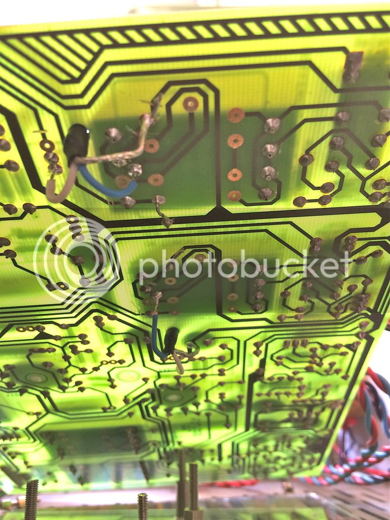
Mistakes I should correct, pin 5 on both trannies looks unconnected!  :eek:,
pin8 on the bottom 1538 looks unconnected.

Anyone else ever used the LL1538 and cares to tell what he/she did?


Am I correct in assuming it should be :
primaries unchanged to the 1528 version
secondaries connected as follows,  pin5 and 8 to earth, pin 6 to the DI-jack?
 

Latest posts

Back
Top