The official G9 help thread

GroupDIY Audio Forum

Help Support GroupDIY Audio Forum:

This site may earn a commission from merchant affiliate links, including eBay, Amazon, and others.
JingleDjango said:
Thank you! And I'm using a  DPST toggle switch on the mains. I'm assuming I should run Grey/Brown & Blue/Violet each to their own terminal on the switch, rather than just the Grey/Brown shown in the diagram?

What you can do is simply wire one side of the switch as shown on the diagram. If you want to disconnect both common and v+ then you use a dpst switch.  I dont have  the diagram in front of me but you look to be right
 
Just finished my G9. HT is 241vdc, heaters are about 11.2vdc. No noise at all, no hum at all, too. Really clean . The only thing is that channel one doesn't work for now (no signal passing through). Only channel 2. Must be some stupid mistakes. I noticed when I turn the mic/line/48v switch, I saw a little signal jump on my DAW's meter bar, which would have lead me to thing that signal is able to exit the unit, so it mut be between input xlr and input transformer...but the DI doesn't work, too. Weird. :eek:

Maybe I miswired the inst. when I did the mod, that would be one explanation

Oh and my phantom sit at 40V with trimmet at max, I don't think it's really an issue since channel 2 works fine. Maybe the input current si a little lower than what is needed, due to the fact I used one transformer with 2x15v secondary to feed the secondary of the second transformer (12v) I know some folks used both transformer at 2x15v, maybe it help getting the right current? Or 40V is just ok and nothign to worry about?
 
ok folks, never mind, it's a bad tube. I swap the tubes and everything is allright. Don'T know what happened to the tube.  It just don't glow. Just took again my phantom power and it's set at 41,5v. I know my tranformer are a little overrated (50VA each) and my AC is at about 17v, so after rectification, I'm about 90v. Anyway, it works and it sounds really cool! I'll update some pictures soon
 
Congrats on a successful build! My li'l guy is coming together nicely. Today I mounted the standoffs in the bottom  panel (first time countersinking anything), mounted IC2 onto a heatsink and stuck that assembly to the back panel.

I'm waiting for a crimp tool to come in the mail to wire the molex connectors. I'm hesitant to do it with just pliers because the headers and crimp fins are so tiny and delicate.

Hopefully there are no expensive faulty components here because I've literally poured all of my disposable income into this project in the past month and I just started a full-time sound engineering program so there's not much in the way of time or income in the near future!
 
JingleDjango said:
BTW, what's the best way to trim the shafts of the Lorlin switches? I've never worked with these before.
Any kind of saw / dremel / knife. It is pretty easy to cut.

Note: hook the thing up at the root of the shaft not from the switch body so you don't kill the innards while sawing!:)
 
JingleDjango said:
BTW, what's the best way to trim the shafts of the Lorlin switches? I've never worked with these before.

I'm using a wire cutter like this: http://www.banggood.com/Craft-Electric-Cable-Wire-Cutter-Plier-Stripper-Electrician-Home-Tool-160mm-p-1012982.html

Jakob E.
 
I have a question about the rotary switches that I hope isn't too obvious:

The models I ordered were CK1049 and CK1050. These are the only approximate Lorlin models available to me.
CK1049 is a 12pos with a single center pin and it seems to be a perfect match. (Or rather, the remaining 3 center pins appear to be 'clipped' at the factory.)
CK1050 has two center pins, rather than the 4 that the PCB has holes for.
I expect that I can use the CK1050s, oriented the same way as the CK1049s, and set to either 2 or 3 positions as the BOM suggests. I just want to be sure these models are appropriate before I solder them in. Should they work as expected?
 
You sre ok. There is no need to get the model with 4 pins because they are 4 poles models, you only need single and double poles so you are ok.
 
Here is the obverse.

I didn't notice until after soldering in the input select switch that the two poles of the switch do not connect to the traces if they sit like this. The other two switches are fine. The poles are labeled A and C. I need to remove this switch and reorient it but my question is, does it matter how it's oriented so long as they both connect? Into which hole should I place pin A?
 

Attachments

  • Lorlin-2.jpg
    Lorlin-2.jpg
    190.2 KB
Here is my build:

12243241_887221298029492_4054673807578783934_n.jpg


12241321_887221408029481_3955169235417472244_n.jpg


12234876_887221424696146_2831133097106167965_n.jpg


12249850_887221364696152_6086185496682515140_n.jpg
 
Hi, I don'T have a really good shot of the overall circuit. I can take one shot tonight, thought. I went with Edcor at the output because I like to have a little coloration and also, they are dirt cheap. I use Edcor as output transformer on a lot of project and they always work nicely. Originally, I planned to use Cinemag transformer at the input, but I had to make some on Newark, so I decided to go with OEP and take advantage of it and pay shipping once. Here in Canada, shipping, handling, border fees, taxes, rates, etc. are pretty expensive from time to time. Lundahl transformers cost a fortune here.
 
I went with OEPs from Newark for the same reasons. They were the only place I could find the Lorlins and get them to Toronto at a reasonable price. Can you tell me how you fixed C1 4 & C15 to the bottom panel? Do those caps have a screw mount on the bottom, or did you use a glue of some kind? I'm still trying to work out some of this practical stuff for my own build.

Your front panel looks really handsome.
 
Some of the specs:

- Input is OEP
- Output: Edcor WSM 2.4K:600
- Caps are polypropylene where applicable, lytics are all Nichicon.
- Power caps C14 and C15 are 470UF each
- Power transformer are Triad, 50VA each. One is dual 15V secondary and the other is dual 12V secondary
- Power supply mounted on the main pcb.
- Ground scheme is the one stated all over the thread: Ground taken at XLR 1 pin 1 and go to IEC bolt, taking all xlr's pin 1 , too. Only XLR 1 has it's pin 1 strap on the main board.
- Board is install as far from the toroid as possible.
- Power caps are installed as close from the board as possible.
- Toroid are installed vertically on the side panel, side by side.
- Pairs of wires are tightly twist
- Instrument mod is done
- Absolutly no noise, hiss, hum, etc. Really clean, nice coloration.
 
JingleDjango said:
I went with OEPs from Newark for the same reasons. They were the only place I could find the Lorlins and get them to Toronto at a reasonable price. Can you tell me how you fixed C1 4 & C15 to the bottom panel? Do those caps have a screw mount on the bottom, or did you use a glue of some kind? I'm still trying to work out some of this practical stuff for my own build.

Your front panel looks really handsome.

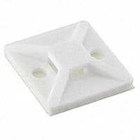
Fixing the caps where pretty easy :) I used a cable ties, fixed on the side panel, behing the caps and simply strap a Tyrap around them.

MB3A10M4_sml.JPG
 
Back
Top