the Poor Man 660 support thread

GroupDIY Audio Forum

Help Support GroupDIY Audio Forum:

This site may earn a commission from merchant affiliate links, including eBay, Amazon, and others.
You know Ive put at least a 200 hours on mine also 10-12 hours at a time with the edcor all my voltages are still dead on it would be be nice if other people with solid units would speak up so we can get to the bottom of whats going on it be a shame to redesign the wheel if it's rolling just fine just my 2c. It sucks for everyone having problems.If their is any info I can contribute I'll be happy to do so just let me know what to do.
 
I've had no PSU problems so far. Not run the unit for more than 2 hours though.
I've a toroid from the European/Holger groupbuy. I only power 1 heater from this toroid. The other heater is powered by another 8A 9V toroid.
Both toroids don't get hot, mildly warm maybe. I do have the slow start heater PSU's.
I think I'll put a NTC before both toroids to get a "slower" start and less inrush current. This way the mains fuse can be scaled down to a better value as well.
 
rrs said:
if we can get over this I do believe this compressor "PM660MK2" ?? could be one everyone will be proud of.

Why wait when you can DIY. This is a place for such endeavors afterall.

http://www.groupdiy.com/index.php?topic=41807.0
 
idylldon said:
I don't know if it makes a difference, but I don't use the soft/slow-start board.  

Cheers,
--
Don
I am using the same transformer as you as well as no slow start board.
Want voltages do you get coming into Q4. Mine seem high around 390-400V.

Our mains here are 240V and the voltages coming from the toroid are a little high to start with.
 
rrs said:
Want voltages do you get coming into Q4. Mine seem high around 390-400V.


About 4 posts up, I posted a link to the HV PSU schematic with voltages for every part of the PSU...

Just for your reference  Q4, pin 1 = 256V, Pin 2 =386V, Pin 3 = 251V

PM_PSU_schemo_WReads.jpg


Thanks so I guess that's not far off mine though we have different transformers. 386V is not far of mine which can differ from day to day 390/400V I am guessing considering Q1,2,3 and some of the caps in the bom are spec'd under this I assume the design didn't account for such high voltages.

They seem to be working for many though and I know first haved that it can work .... for a while.
 
If you bump up C2 and C3 to (Edit to 450V) you would be doing good. Speaking of which I just looked at my PSU and I have 350V on Electrolytics and 630/400V on the Films, so even my PSU is a little under specifications.

I don't know what crazy voltages are there on startup, but in working conditions I don't see more than 130V in any C-E or C-B connections, which is under the 300V spec for the parts listed.

http://www.fairchildsemi.com/ds/MM%2FMMBTA92.pdf
http://www.fairchildsemi.com/ds/MP/MPSA42.pdf

Edited: from Analag's response from 400-450V
 
Transistor question: when the max collector emitter voltage is 300V, does that mean a  difference of 300V maximum between collector and emitter?
 
A good way of dealing with surge is to put a resistor or choke between the rectifier and first filter section. "Remove C6 immediately". C6 should NOT be an electrolytic cap and 1uF is the MAXIMUM value recommended. At start up C6 shorts out R7  which drags down the regulated voltage far too low (100V) for too long. There is no slow start feature in this design. And why would C1 and C3 be anything less than 450V.
 
analag said:
Why would C1 and C3 be anything less than 450V.

The PSU BOM calls for 400, which actually covers it, but it's almost at it's rated breakdown point.


Any ideas on how much resistance/ Wattage  is needed to deal with that surge? Just a guess but not much say under 1K .... ? Trying to understand it's purpose, I'm thinking the resistor/Choke is just limiting the charging of C1 and on?

Without moving C1 off board you could kludge the surge resistor possibly between  a common connected striped end of D3 and D4 lifted off the board.
 
analag said:
"Remove C6 immediately". C6 should NOT be an electrolytic cap and 1uF is the MAXIMUM value recommended. At start up C6 shorts out R7  which drags down the regulated voltage far too low (100V) for too long.

So basicly, C6 should be replaced with a 1uF (or less) poly cap?
 
kazper said:
Any ideas on how much resistance/ Wattage  is needed to deal with that surge? Just a guess but not much say under 1K .... ? Trying to understand it's purpose, I'm thinking the resistor/Choke is just limiting the charging of C1 and on?

Without moving C1 off board you could kludge the surge resistor possibly between  a common connected striped end of D3 and D4 lifted off the board.

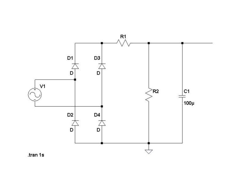
Break the trace between D3/D4 and C1. I suggest a 10W wire wound 50R or more, shunt C1 with about 150K or less. You will have to go off board with these.

radiance said:
So basicly, C6 should be replaced with a 1uF (or less) poly cap?

Exactly, with .47uF as my favorite value.
 
Example1.jpg


R1 should be 10W 50R  - 100R and R2  2W 150K - 75K depending on your situation. Tweak the values so that you have 310V - 320V going into the regulator under full load meaning when the tubes are conducting/working or whatever you wanna call it.

 
I assume the c1 value (100uF) on the mod shem is not important and represents c1 (220uF) from the original psu?
 
tomcat said:
I assume the c1 value (100uF) on the mod shem is not important and represents c1 (220uF) from the original psu?

Go with the original schemo, the other one was just an example of how to deal with the voltage issue some builders are having.
 

Latest posts

Back
Top