the Poor Man 660 support thread

GroupDIY Audio Forum

Help Support GroupDIY Audio Forum:

This site may earn a commission from merchant affiliate links, including eBay, Amazon, and others.
So I got around to doing my poorman stereo box. Was going to sell them but changed my mind.

I figured I was up for the challenge after all. See if I could tame this reported b*tch from hell's kitchen.

Anyway, built it stock with edcor psu traffo, 240Vac/50Hz line voltage.
I included the change to C6 as recently suggested.

Powered up first time today.

No smoke, no noises, no probs with either of the 245Vdc or 135Vdc.
Heater was easy to adjust to get 6.35Vdc with an ohmite rheostat.
Both pairs of 5687 installed caused no probs.

No excessive traffo heat. 5687s get hot but not the raging inferno I expected.
(23C ambient, lid off). Heater resistor gets hot, but managable.
I have a 3ru case with a fair bit of ventilation slots top, bottom and sides.

I ran it for a hour and a half - all good and passing audio from the get go.

Early quick check showed a unity gain noise floor of around -65dBu or so with no compression.
That's OK but not great. Had  good sized mains harmonics. But it's early days yet.

I'll be checking the compression and all that tomorrow. Then trying some tube matching
and subs (I have some 6N5P on the way as well as another bunch of 6BC8).

If I can get some good sound, I'll then try the scamp addon and some time constant combinations.

Early indications are for me that this went together and powered up exactly as 'advertised'.

Will see how it goes over a couple of days of tinkering.

Hopefully I haven't jinxed it by making this post. This build seems to have it's fair share of
negativity so I thought I'd give an account of my experience 'hot off the presses'.

Cheers
 
Glad to read this, even it is the 2nd time today :D

(the first time was in an email from another member / builder ;))

however, you know what we always want: PICS ;D ;D ;D
 
As requested  ;D

All finished.  Everything seems to work perfectly.  I think that sorting the meters and a couple of wiring mishaps were my biggest problems.  Still obviously need to finish the front panel.  I've got a friend in a sign shop doing vinyl lettering for me, but he's a little hard to motivate sometimes.  Damn artists!!  But I need to keep him happy because they're getting a laser engraver pretty soon that I plan to make good use of :)

pm670-4.jpg

pm670-1.jpg

pm670-3.jpg

pm670-2.jpg
 
looks nice man. 

Curious about your "wiring mishaps" and VU issues. Were the problems with the VU just the parallel resistor?

I know yours is working but according to Analag's recent posts, you should change your PSU C6. He recommends 0.47uF.
analag said:
..."Remove C6 immediately". C6 should NOT be an electrolytic cap and 1uF is the MAXIMUM value recommended. At start up C6 shorts out R7  which drags down the regulated voltage far too low (100V) for too long...
 
argh, nice & clean build, looking forward to see it with the finished front panel ;D

mitsos said:
I know yours is working but according to Analag's recent posts, you should change your PSU C6. He recommends 0.47uF.
I'm sure Analag is referring to the non-working units only.
the PCB reflects his initial design, we don't need to change anything in all the working units.
at least I won't open mine up again :eek:
 
[silent:arts] said:
I'm sure Analag is referring to the non-working units only.

No, Analag is refering to the PSU schematic, which has been made public after several people had PSU Failures.
PSU's in working and non working units are all the same so it's only a matter of time/luck before a failure will occur.

[silent:arts] said:
the PCB reflects his initial design,

Did you do the actual design?


mitsos said:
looks nice man. 

Curious about your "wiring mishaps" and VU issues. Were the problems with the VU just the parallel resistor?

I know yours is working but according to Analag's recent posts, you should change your PSU C6. He recommends 0.47uF.
analag said:
..."Remove C6 immediately". C6 should NOT be an electrolytic cap and 1uF is the MAXIMUM value recommended. At start up C6 shorts out R7  which drags down the regulated voltage far too low (100V) for too long...

Thanks, Mitsos.  Wiring problems were just my stupid mistakes.. nothing major, just took some head-scratching to figure out.  And yeah, the VU was just getting the parallel resistor right.  I wound up taking it off the board entirely, and you can see the trimmer which is a 500R up on the GR/Out switch.

As for the PSU, mine works just fine as is.. had it done before any of that talk regarding components.  Like Volker said, I sure don't want to take mine apart if I don't have problems!

[silent:arts] said:
argh, nice & clean build, looking forward to see it with the finished front panel ;D

Thanks, and me too!  It's funny, par-metal sent me that anodized front by accident.  Not what I ordered.  I really didn't like it at first, but now I think the kind of gold color with the black trim looks nice.  I guess it grew on me.
 
radiance said:
[silent:arts] said:
I'm sure Analag is referring to the non-working units only.
No, Analag is refering to the PSU schematic, which has been made public after several people had PSU Failures.
yes, I talked him to make the schematic public

radiance said:
PSU's in working and non working units are all the same so it's only a matter of time/luck before a failure will occur.
wrong. we have quite a lot builders without any errors. either they don't post or they have no failures after 2 years.
the initial schematic and design works proven well.
I will do a little research if needed, but if my memory is right most failures happened with modified builds.

radiance said:
[silent:arts] said:
the PCB reflects his initial design,
Did you do the actual design?
no
 
[silent:arts] said:
radiance said:
PSU's in working and non working units are all the same so it's only a matter of time/luck before a failure will occur.
wrong. we have quite a lot builders without any errors. either they don't post or they have no failures after 2 years.
the initial schematic and design works proven well.
I will do a little research if needed, but if my memory is right most failures happened with modified builds.

I'm sorry but I think you don't get what I'm saying here.
I said that all PSU's in working or non working units are the same. I don't recall many people have modified their PSU's do you?
Also, I don't think that PSU failure is linked to modified units...but than again, a well designed PSU should handle this as well.


Another thing, if the initial PSU schematic & design works well, why is it that all of a sudden Analag strongly suggested to replace C6?
 
radiance said:
I'm sorry but I think you don't get what I'm saying here.
may be

radiance said:
I said that all PSU's in working or non working units are the same. I don't recall many people have modified their PSU's do you?
sure they are the same (I'm not aware of any modified PSU).
why do most work?

radiance said:
Also, I don't think that PSU failure is linked to modified units...
I will do the research

radiance said:
but than again, a well designed PSU should handle this as well.
wrong. a PSU is designed for its specific use, not for its abuse.
if there are any modifications always consider the PSU.
Analags PSU works very fine in stock units.

radiance said:
Another thing, if the initial PSU schematic & design works well, why is it that all of a sudden Analag strongly suggested to replace C6?
might be the easiest fix for builds with problems?
I don't know. let us wait for him to answer himself.
 
One more issue with the original psu which I don't recall reading anywhere, is that the capacitance used for the filtering of the heater supply is nowhere near enough for the currents involved.

If you are putting together a stereo unit you need at least 10000 microfarads in addition to the ones in the pcb.

What I have done is put two extra capacitors in parallel to the stock ones using the screw terminals for the cables.
After that hum went away.

 
analag said:
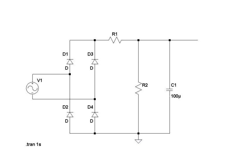
A good way of dealing with surge is to put a resistor or choke between the rectifier and first filter section. "Remove C6 immediately". C6 should NOT be an electrolytic cap and 1uF is the MAXIMUM value recommended. At start up C6 shorts out R7  which drags down the regulated voltage far too low (100V) for too long. There is no slow start feature in this design. And why would C1 and C3 be anything less than 450V.

analag said:
Example1.jpg


R1 should be 10W 50R  - 100R and R2  2W 150K - 75K depending on your situation. Tweak the values so that you have 310V - 320V going into the regulator under full load meaning when the tubes are conducting/working or whatever you wanna call it.

So to recap....

PSU issues:
BOM is incorrect for C1 and C3 Voltage should be 450V
C6 is a Electrolytic and should be a Film 1uf Max, but 0.47 Uf is best... so C6 = 0.47 uf 350-400V Film cap.

Possible Surge on startup issues:
Add R1 10W - 50R to 100R and R2 2W 75K-150K as shown... and in another post the Analag the designer said C1 is original schematic value of 220uf not the 100uf as shown in the diagram above.

You really want to read page #128-129....
 
After looking extensively through the thread I don't recall anyone modding the PSU apart from the slow start heater.

I assume a power supply for this is hard to design taking in consideration what is best for audio quality, cost and functionality. I have someone else looking at mine at the moment an will hopefully have a reliable unit back in my hands soon.

Hopefully a small mod can be done to make the PSU more reliable soon. I assume those who have working units will be fine without mods but the parts are close together and will get hot. Surges may also take out smaller components. Many issues have been identified through the thread but may be only matter of opinion.
 
I've had no issues with the power PSU,  both a green one and a white one. I've got Edcor Power Transformer mounted on the outside of the enclosure, and I have the power switch back there too. No slow start boards, Heater resistor is .5 Ohm 100W,  a silent DC fan is running off the +12V relay power rail, keeps it very cool. Star Ground is a little different in that the chassis connection point is immediately below the edcor.
 

Attachments

  • DSC00040.jpg
    DSC00040.jpg
    32.4 KB
PS - Horvitz : what a completely great wiring job on your poorman!
     You set a fine standard for build quality.

Here's pics of the poorman 670 which I began testing last night.

poorman_outside1.jpg


poorman_inside3.jpg


Another 5hrs of testing, with lid on, 22C ambient - no probs with heat, just good
and warm on the outside lid. All voltages good and stable, no psu issues at all.

GR meters calibrated fine with 2K parallel pot, pretty accurate to around 1-2 dB of GR.
Set the trimmers to -2.4V (RV3) and -4.5V (RV4) no prob.

Checking the performance with unmatched 6BC8 tubes - I have a total of 4 right now !
I have some mismatches between the channels - I'm just now checking the CVs and so on.

I get easily around 12dB or GR and I can make up gain for it with no problem.

My basic unity gain noise floor is now (post calibration) -74dBu with no GR (ie. no makeup) which is excellent
and -68dBu with 12dB of compression (ie. 12dB of makeup) which is pretty damn good.
The channel closest to the psu is not as good and I'll be focusing on that.

Bypassed noise floor is -83dBu which is basically  the Motu noise floor.

Frequency response (both channels) is basically flat to 20Hz and down 3dB at 20KHz.
No big roll offs here!

Apart from the channel mismatch, and some noise optimisation I am yet to do,
it's all behaving like a real lady. Nothing twitchy or anything.

I have got some detail checking to do, but that aside, I've been listening to it thru a Motu2408mkII
into a 20W el84 pp stereo amp (circa 1965) and 3way hifi speakers, which is my standard testing setup.

================

Well I have to say first and formost it sounds *completely excellent* with elec guitar
(noiseless pups, LR Baggs Paracoustic, balanced output).

I have yet to test it with a mix, so no comment there yet.

The compression is very transparent, almost unnoticeable, I guess partly due to the long attack and release.
Seems to have at least 10s release time and definately doesn't grab transients noticably.
I can't hear the compression much at all.

But it is doing around 12dB of GR.

I didn't hear any real distortion - just pure sound with real weight and authority.

I could easily end up using this all the time for guitar. It is so transparent it makes
my la2as sound 'obvious'    (no offence there! I love my la2as)

For my first ever usage of a vari-mu I have to say "baby I'm amazed"

=============

Hats off and much thanks/respect to Analag, SilentArts and all the other contributors
to this fine unit and to the vari-mu knowledge base in general.

I hope my future builds work out this good!

I'll be testing, tweaking noise and balance, listening and then modding this unit for
some time to come. I think the potential is really there for this to be my No1 fav comp.

Poorman 670 - it just rocks!

Cheers
 
Finally - my name up in lights!

Well, I moved some things around and now get the noise floor on the channel closest to the psu
to be within 5dB of the other - so it's all operating pretty quiet now.

I see around -62dBu with around 14dB of make up gain over unity and around -72dBu at unity
for the channel closest to the psu.

----
(that noise floor figure is an rms, aggregated figure for the whole spectrum, using the
dBu standard on a soundcard calibrated to absolute voltage using a cro with 5mV per division.
The individual 50Hz and 100Hz noise peaks are around -80 and -85dBu respectively

Other analyzers report significantly 'better' figures as they use dbFS type of measurement

I feel that the dBu figures are much more realistic. After all, we talking of voltages of
less than tenths of millivolts here! Just about anything can cause fluctuations of that level)

----
That's pretty darn good and I am pretty happy with it. I tried some steel plate shields
and that was good for around 1.5dB reduction - not sure it's worth it. I notice putting the lid
(steel) on raises the floor around 3.5dB! which is a pisser.
Using aluminum sheet doesn't alter the noise floor at all. So - time to fab an alu lid!

Anyway - I modded one channel to the 2 rotary switch 'bluebird' time constants network
using resitances of 26K to 470K and then open in parallel with 0.47uF to 6.8uF and then the onboard
10uF.

Happy to say  WOW  ;D ;D ;D

Routinely getting around 15dB of compression, with fast release before I notice the distortion
creeping in. Definately getting a nice firm but spongy response (which is a good thing!)

Can get a pretty fast release now, maybe 0.5s or so. Attack seems faster but not as
noticable as the change to the release time. I'll be doing some more detail checking now.

Next up is some crude tube matching/sub and into the small studio (lounge room    :D)
for getting familiar with the sound and all that.

So far it's been a dream run. (touch wood!)
 
Huge win with a little more rearranging of wires and input/output traffo positions.
No metal shields neccessary! And the steel lid on now makes no difference to noise!

I now have a unity gain noise floor of -79dBu and -78dBu. Bypassed it is -83dBu each.
50Hz and 100Hz all below -90dBu now.

The Poorman 670 is now officially my quietest unit yet with respect to mains noise.

;D ;D ;D
 

Latest posts

Back
Top