TMI about square waves

GroupDIY Audio Forum

Help Support GroupDIY Audio Forum:

This site may earn a commission from merchant affiliate links, including eBay, Amazon, and others.
isn't a square wave all the odd harmonics?

Yes - with a mathematical relationship between them as JR has detailed.
But just wanted to say that it's interesting if you phase/time shift the harmonics relative to each other.
You then get the same harmonic spectrum but without the extreme rising/falling edges.
IIRC this was (is I guess) used by some synth' manufacturers to produce 'square waves' - Korg comes to mind ?
 
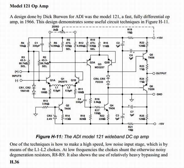
Burwen used emitter inductors in the ADI 121 in 1966 15 years prior to Jensens's patent.

https://www.proaudiodesignforum.com/forum/php/viewtopic.php?f=12&t=675&p=7820
ADI_121_Dick_Burwen_Emitter_Inductors.JPG
 
Duh, "DOA", of course, I am quite familiar with discrete opamps.. just not aware it was a commonly accepted abbreviation.. (RTFM, TL;DR, SMH, LOL FWIW..!)

DOAs are a hot topic for the cork sniffers..!

I have a pair of Melcor line amps with 1731s, which were an obvious predecessor to the API 2520. I mention this because the typical lay-person / cork sniffer on the internet often describes the API "sound" as having "fast transients" [sic] or being a "fast sounding" opamp.
We know otherwise, but it does bring up some interesting questions about perception (which these days we must divide into *empirical* perception or *induced* perception via group think on teh internetz).
For me one of the defining characteristics of a "DOA" is the overload recovery behavior. A 2520 can add a certain "oomph" to a drum when driven hard, where a 990 will just present a louder version of the event. All of this is somewhat relevant to Square Wave reproduction..

Stability issues are often revealed by using square waves

1k Square Wave through A/D/A loop:1kHz converter loop at 96kHz.jpg

1kHz Melcor 1731 at 96kHz
1kHz Melcor 1731 at 96kHz.jpg


Melcor AML-27 30kHz ringing.jpg
 
not sure what a cork sniffer is but ASSume its pejorative (wine corks?).

DOAs were a useful practical design tool back in the day. Today they are kind of a throwback to earlier times, but we have seen some good work done with modern DOA designs this century. Different strokes for different folks.

JR
 
were an obvious predecessor to the API 2520. I mention this because the typical lay-person / cork sniffer on the internet often describes the API "sound" as having "fast transients" [sic] or being a "fast sounding" opamp.
We know otherwise, but it does bring up some interesting questions about perception (which these days we must divide into *empirical* perception or *induced* perception via group think on teh internetz).
For me one of the defining characteristics of a "DOA" is the overload recovery behavior. A 2520 can add a certain "oomph" to a drum when driven hard, where a 990 will just present a louder version of the event. All of this is somewhat relevant to Square Wave reproduction..

Stability issues are often revealed by using square waves

1k Square Wave through A/D/A loop:

1kHz Melcor 1731 at 96kHz
Yes, ringing/overshoot can make a signal appear more powerfull.

When I had GAR1731s on my mixbus it made the mixing experience more pleasant by presenting a punchier output from the start and masking some elements sticking out too much. However, the end result always sounded off, grainy, in the high end. A clean mixbus and the operator working harder ultimately results in a better mix.
 
Duh, "DOA", of course, I am quite familiar with discrete opamps.. just not aware it was a commonly accepted abbreviation.. (RTFM, TL;DR, SMH, LOL FWIW..!)

DOAs are a hot topic for the cork sniffers..!

I have a pair of Melcor line amps with 1731s, which were an obvious predecessor to the API 2520. I mention this because the typical lay-person / cork sniffer on the internet often describes the API "sound" as having "fast transients" [sic] or being a "fast sounding" opamp.
We know otherwise, but it does bring up some interesting questions about perception (which these days we must divide into *empirical* perception or *induced* perception via group think on teh internetz).
For me one of the defining characteristics of a "DOA" is the overload recovery behavior. A 2520 can add a certain "oomph" to a drum when driven hard, where a 990 will just present a louder version of the event. All of this is somewhat relevant to Square Wave reproduction..

Stability issues are often revealed by using square waves

1k Square Wave through A/D/A loop:View attachment 85608

1kHz Melcor 1731 at 96kHz
View attachment 85609


View attachment 85610
Some would consider the linearity or accuracy of reproducing a 30kHz square wave as unrelated to audio sound quality because all the overtones are above human audition. That said HF nonlinearity can and does create audible intermodulation distortion products down in the audio pass band. The most common audible differences are simple frequency response. Awkward recovery from brief transients that saturate the output can cause longer duration transient artifacts that are more audible than clean recovery.

JR

PS; I still don't argue with people about what they say they hear.
 
Burwen used emitter inductors in the ADI 121 in 1966 15 years prior to Jensens's patent.

https://www.proaudiodesignforum.com/forum/php/viewtopic.php?f=12&t=675&p=7820
ADI_121_Dick_Burwen_Emitter_Inductors.JPG
I was unaware of the Burwen use but also found it used by Cordell in a power amplifier of the seventies. Deane was apparently unaware of either - as was the US Patent office. I think Deane may have discovered one of these "prior art" examples after his patent issued. It may have been why he was anxious to "give it away" by publicly declaring it public domain in a magazine article shortly after issue. One weakness of the patent office's "prior art search" is that they see only "published" material. Prior art often exists as "confidential" documents like schematics, which manufacturers often carefully guard as "trade secrets." Obviously, the emitter inductors claim would have never withstood a legal challenge.
 
Patent examiners are generally wet behind the ears performing word searches to find claims interference. I encountered one who didn't understand the difference between "currents" and "current sources".

Then there's the patent lawyers... I had one try to discourage me from even doing a patent search. By then we had internet patent searches*** for at least a major fraction of the patent database so I did my own search.

I had one patent issued where I discovered years after the fact that prior art existed. Since I had assigned the patent to my employer for $1, and no longer worked there, it wasn't my place to inform the PTO about the invalid patent. If it was ever challenged I would have come clean.

JR

**** back in the 70s I actually travelled to Arlington, VA. to perform a manual patent search. The old paper patents were stored in shoes (wood drawers) by category. It was very time consuming and easy to miss something.
 
Some would consider the linearity or accuracy of reproducing a 30kHz square wave as unrelated to audio sound quality because all the overtones are above human audition. That said HF nonlinearity can and does create audible intermodulation distortion products down in the audio pass band. The most common audible differences are simple frequency response. Awkward recovery from brief transients that saturate the output can cause longer duration transient artifacts that are more audible than clean recovery.

JR

PS; I still don't argue with people about what they say they hear.
Perhaps I wasn't clear enough, my apologies... Those scope photos were of a 1k square wave. The ringing shown when driven by a 1kHz square wave in the Melcor circuit is at 30kHz. The waterfall graph is a sine wave sweep with a bandwidth of 96kHz, it also excited the resonance at ~30kHz.

And yes, IMD is a real problem..

Literally every project I have received to mix that is recorded at 88.2, 96 or 192 (have not seen any 176.4 yet) have ultrasonic signals present in at least one of the tracks. I typically notice these when an acoustic instrument sounds 'off' or drum overheads sound shrill or have an unnatural 'metallic' overtone.
Then I pull out the spectrum analyzer and look at what's going on in the ultrasonic region. I uniformly find some steady tone, or even several tones anywhere from 30kHz to 80kHz (in a 192k project), and these tones - which may be from a phone, or here in the city, literally from anything, are causing IMD in the *audible* spectrum.
An apt analogy for this would be to say that recording at higher sample rates without regard to your studio's wiring, grounding, RFI immunity, etc, is like driving your grandmother's car at 120mph down a neighborhood street, or putting a Ferrari engine in her car and thinking that this alone has turned it into a racing car.
 
Last edited:
Perhaps I wasn't clear enough, my apologies... Those scope photos were of a 1k square wave. The ringing shown when driven by a 1kHz square wave in the Melcor circuit is at 30kHz. The waterfall graph is a sine wave sweep with a bandwidth of 96kHz, it also excited the resonance at ~30kHz.

And yes, IMD is a real problem..

Literally every project I have received to mix that is recorded at 88.2, 96 or 192 (have not seen any 176.4 yet) have ultrasonic signals present in at least one of the tracks. I typically notice these when an acoustic instrument sounds 'off' or drum overheads sound shrill or have an unnatural 'metallic' overtone.
Then I pull out the spectrum analyzer and look at what's going on in the ultrasonic region. I uniformly find some steady tone, or even several tones anywhere from 30kHz to 80kHz (in a 192k project), and these tones - which may be from a phone, or here in the city, literally from anything, are causing IMD in the *audible* spectrum.
An apt analogy for this would be to say that recording at higher sample rates without regard to your studio's wiring, grounding, RFI immunity, etc, is like driving your grandmother's car at 120mph down a neighborhood street, or putting a Ferrari engine in her car and thinking that this alone has turned it into a racing car.
Cleanly reproducing above band signals is an alternative to effectively LPF the signal down to the human hearing range. Of course depending upon upstream signal chains these above band signals can stress circuits that may create in-band artifacts (IMD). My preference is to bandpass signals appropriately in front end circuits to avoid the risk of depending on other designers to do the heavy lifting. Making their work easier can improve the entire audio chain's sound quality.

JR
 
That's the main reason why I do most of my projects at Double Speed (88.2/96K SR). Most of the signals coming from mics have significant ultrasonic content up to about 40kHz, particularly drums & percs, acoustic string instruments, piano... When recording at Single Speed (44.1/48k), it's the converters that do the heavy lifting, and generally the user has no control of the anti-aliasing filters; whatever sonic damage happens then is printed and not recoverable.
At Double Speed, there is very little energy above the Nyquist frequency, because of the natural roll-off of the source spectrum and of the microphones roll-off, thus it results in very little artefacts added to the signal.
Keeping the project at Double Speed and changing the sampling rate at the last step of production, allows selecting a more robust resampling algorithm.
After that, I'm perfectly happy with the 15us rise-time of 44.1k SR, and the rest of the equipment too.
 
Last edited:
The ringing shown when driven by a 1kHz square wave in the Melcor circuit is at 30kHz.

And yes, IMD is a real problem..
I think you could identify and resolve these issues.

The Melcor was probably designed with 600 ohm load in mind. I don't know anything about those but presumably they were driving a bus in a console and not a long cable with 10K load. What is your load on the output? Try strapping a 1K resistor on the output and see what happens. I bet that ringing goes away completely.

Nowadays it's customary to have series resistance of 30 - 100 ohms with the output of a line amp. The emitter resistors on DOAs are usually a little small. IC amps have better open loop gain and output swing so they can afford to use higher values. Otherwise, if your output Z is less than 10 ohms or so, driving a long cable into 10K might easily produce ringing.

I would get severe OCD if I found artifacts like that. It's probably good that I don't have a audio interface that goes that high.
 
Perhaps I wasn't clear enough, my apologies... Those scope photos were of a 1k square wave. The ringing shown when driven by a 1kHz square wave in the Melcor circuit is at 30kHz. The waterfall graph is a sine wave sweep with a bandwidth of 96kHz, it also excited the resonance at ~30kHz.
I would bet such a ringing can be seen in the frequency response.
 
That's the main reason why I do most of my projects at Double Speed (88.2/96K SR). Most of the signals coming from mics have significant ultrasonic content up to about 40kHz, particularly drums & percs, acoustic string instruments, piano... When recording at Single Speed (44.1/48k), it's the converters that do the heavy lifting, and generally the user has no control of the anti-aliasing filters; whatever sonic damage happens then is printed and not recoverable.
Are you hearing artifacts related to aliasing? I thought most modern convertors performed the initial conversions at extremely high sample rates where effective antialias filters can be low order and well behaved. The final output sample rate is a function of how the high frequency samples are decimated.
At Double Speed, there is very little energy above the Nyquist frequency, because of the natural roll-off of the source spectrum and of the microphones roll-off, thus it results in very little artefacts added to the signal.
Keeping the project at Double Speed and changing the sampling rate at the last step of production, allows selecting a more robust resampling algorithm.
After that, I'm perfectly happy with the 15us rise-time of 44.1k SR, and the rest of the equipment too.
Back in the day an old trick to check for HF IMD in a studio audio path was to jangle a key chain in front of a microphone, those keys could make content even higher than 40kHz. I also recall being able to trick the old ultrasonic TV remote channel changers with jangling keys.

JR
 
Are you hearing artifacts related to aliasing?
I don't like what I hear when I track at Single Speed, which I do only when working on projects that have been started elsewhere. I guess the real-time ALU in the chip has a harder time than that of the computer that does the final conversion. I use Samplitude, which offers 4 different native downsampling algoriths, and allows using almost any other. I don't care if the conversion takes several minutes.
I thought most modern convertors performed the initial conversions at extremely high sample rates where effective antialias filters can be low order and well behaved.
You're right about the initial conversion, but the decimation is still a subject of debate. When it's hard-coded in the chip, you have no choice. Newer convertors offer the possibility of selecting or even customizing the decimation filter but not many multitrack converter offer that.
Back in the day an old trick to check for HF IMD in a studio audio path was to jangle a key chain in front of a microphone, those keys could make content even higher than 40kHz. I also recall being able to trick the old ultrasonic TV remote channel changers with jangling keys.
Some percs can do that, triangle, chimes, cymbals... It is the responsibility of the SE to make sure offensive frequencies are tamed down, with judicious choice and positioning of microphone and use of LPF.
 
One might be tempted to run some experiments with stressful test signals.

Aliasing could be parsed out with HF sine waves, HF IMD with two tone or multi-tone IMD test stimulus....

Of course I don't work in those trenches these days and only have an academic interest, so YMMV.

JR

edit--- mic distance is an effective LPF /edit
 
One might be tempted to run some experiments with stressful test signals.

Aliasing could be parsed out with HF sine waves, HF IMD with two tone or multi-tone IMD test stimulus....
That's what Dan Lavry did some time ago. In short, his conclusions were that most converters didn't provide adequate performance at Single Speed, when they were adequate at Double Speed. Indeed, converter chips have evolved a lot since, but many use converters with relatively ancient technology.
In my case, I use a 2007 Tascam D4800, so the technology is probably about 20 y old.
In order to benefit from new technology, I would need to replace the mixer and add a separate converter, and I would probably continue working at Double Speed, because storage costs so little.
 
If double speed doubles the input sampling rate and not just how the output gets decimated that could improve alias margins. Modern digital technology is so much better than the crude early days.

Do what works for you... disregard my veer.

JR
 
If double speed doubles the input sampling rate and not just how the output gets decimated that could improve alias margins.
It's definitely the case for the AK5385A in the Tascam DM4800. The current high-perf ADC's definitely take advantage of all these possibilities.
I believe the difference I perceive (not really hear) is due to the fact that the anti-alias filters have significant response (-30dB) up to 0.535Fs at Single Speed. So a signal that has significant energy up to 40kHz can result in aliases that are about 40dB below signal. These aliases would be in a 20-30kHz range which we're not supposed to hear, however they can beat and result in non-harmonic content.
At Double Speed, these aliases are of much lower amplitude and shifted above 50kHz.
... disregard my veer.
No. It's a good opportunity to reaffirm basic knowledge.
 

Latest posts

Back
Top