trouble with Green Pre meter section

GroupDIY Audio Forum

Help Support GroupDIY Audio Forum:

This site may earn a commission from merchant affiliate links, including eBay, Amazon, and others.

OddHarmonic

Well-known member
Joined
Jun 7, 2004
Messages
71
Location
Denver, CO
Well, the audio side of my first two Green Pres seems to work just fine, although I haven't REALLY pushed them yet, as I'm moving my focus to the meter sections, which so far are non-functioning. V+/- check out OK on the TL072 and the LM339, with the two ICs OUT, all LEDs light up which Peter indicated in a previous thread as being normal. With the ICs IN, all LEDs stay lit as well. I am stuck on the second step of the Green Pre Setup:

"Setting the Peak detector DC offset (20k Multiturn trimmer).

1. Set the rotary gain switch to minimum gain with no input signal.
2. Attach the multimeter + probe (set multimeter to DC mV) to the link behind the 10k Output Trim pot. The other multimeter lead goes to
+ground.
3. Trim the 20k trimmer to read as close to -3mV as possible. "

TMBG earlier expressed some confusion what link Peter was talking about, and Peter clarified with this pic:

linkpic.jpg


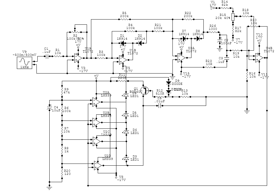
If I'm seeing things straight, this link leads from the output of TL072 #3 to the non-inverting inputs on the LM339. I am measuring 13.85 VDC and this value is not effected by the 20K trimmer. The obvious value that is adjusted by the 20K trimmer is the input to the non-inverting input on TL072 #3. The schematic confirms this. What am I doing wrong here?? Any ideas?

Ah, and here is the schematic:


Green_Meter.GIF


Thanks,
Andrew
 
I'm not at home right now, so I cant get too deep, just some random stuff:

Are the TL 074 & LM 339 in the right way? They sould be opposite to the 5532s.

Check the diodes in the rectifer for polarity.

What freq are you using to test? I use 500Hz or so.

Regards
Peter
 
Thanks Peter, I swear I owe you a beer already and I've only just begun asking questions!! The TL0732/LLM339 are facing correct. I did check the diodes as well, but I will re-check tonight, and perhaps pull them and replace them.

This step says use no input signal. For the first step (CMRR) I was using 100 Hz, and for the third I was using 250 Hz. It may be worth mentioning that I tried to skip step 2 and go to step three just to see if the 100K trimmer would eliminate the "All LEDs on" situation, but it did not.

Andrew
 
Well, the diodes all appear to be orientated correctly, I haven't pulled them and replaced them. Perhaps tomorrow if I'm not so tired.
 
Well, it appears that the first two stages of the TL072 are working correctly. I am seeing amplification that varies with the setting on the 100K Trim. The last two stages I'm unsure about. I'm measuring no real AC voltage at the input or output of those two stages, but plenty of DC. Now, I may be wrong, but the first full-wave redictifer comes right after the second amp stage, so after that, DC should be present instead of AC. However, the last two stages don't vary with the 100K pot, and the fourth stage output is 14.21VDC, instead of a few mV. Here are the voltages for all pins on the TL072, in VAC (with VDC in () if significant) The first set is with the 100K all the way CCW (high-gain) The second set is with the 100K all the way CW (low-gain)

PIN# (CCW, high gain)
1 = 787 mV (-415 mVDC)
2 = 3.5 mV
3 = 3.5 mV
4 = 3.5 mV (14.75 VDC)
5 = 3.5 mV
6 = 3.5 mV
7 = 4.2 mV (-427 mVDC)
8 = 3.5 mV (14.21 VDC)
9 = 4.2 mV
10 = 3.5 mV (9.74 VDC)
11 = 4.2 mV (-14.76 VDC)
12 = 3.5 mV
13 = 3.5 mV
14 = 866 mV

PIN# (CW, low gain)
1 = 3.2 mV (-102 mVDC)
2 = 3.5 mV
3 = 3.5 mV
4 = 3.3 mV (14.75 VDC)
5 = 3.5 mV
6 = 3.5 mV
7 = 3.5 mV (-430 mVDC)
8 = 5.0 mV (14.22 VDC)
9 = 3.5 mV
10 = 3.5 mV (9.74 VDC)
11 = 3.5 mV (-14.76 VDC)
12 = 3.5 mV
13 = 3.5 mV
14 = 3.5 mV

I'll be taking the board to work tomorrow to see if the magnifying glass can see something wrong on the pin side that my eyes cannot. Is there anyway to verify the diodes aren't fried without pulling them from the circuit?

Thanks
Andrew
 
The voltage, AC or DC, at the op-amp 1, 2, and 3 "-" inputs, will always be "zero", since the "+" inputs are grounded and the feedback acts to null the differential voltage across the inputs.

Set up say 5V RMS AC out of opamp 1. The output of opamp 2 should be whacking -5V on half-cycles; it may read -3V on a DC meter. The output of opamp 3 should be whacking +5V. The top of C2 should charge to +5V. When you increase or reduce the AC drive signal, this DC voltage should change in proportion.

Lift one end of R19. Diddle trimmer R15. The output of opamp 4 should swing from about +3.5V to -3.5V.

As you swing that, the outputs of the 339 should switch up or down, and their LEDs should go on or off. I guess R15 alone will not toggle the highest LED, but the D3 LED and that 339 output should flip-flop. It probably flops from full -17V (supply rail) to maybe -15V (and -13V, -11V, -9V for the higher LEDs).

It seems VERY unlikely that the rectifier doides could be burnt. They are tough, and the opamps don't have enough grunt to melt 1N914s.
 
Nice, thanks PRR for giving me some ideas, I'm at work, but I'm excited to head home and run some more tests. I'll report back!

It is worth mentioning, that I have gone through the solder-side of the board visually with good magnification and good light, and have not found anything suspicious, although sometimes the eyes fail.

I find it strange that both channels I built have the same problem. I was measuring componants very carefully as they went in, I matched resistors between the two channels, and have checked/re-checked the orientation of diodes/caps. I made my best attempt to varify the placement of all jumpers with the schematic, in case some were optional (for diff. setup) but I found no problems with placing them all. I am connecting the meter section AFTER the 10K Log Pot, which Peter says works, but isn't the way he normally wires his pre-amps. Anyone out there gone this route instead of before the 10K Pot??

Thanks again PRR!
Andrew
 
ughh.... no progress, just more numbers (at least the Cubs are finally winning)

TL072#1 Out = 5.020 VAC
#2 Out = 3.112 VAC (-2.293 VDC)
#3 Out = 22.1 mVAC (-405 mVDC) There is the first sign of a problem according to PRR's predictions

top of C2 = 2.3 mVAC ~ 101.7 mVAC (9.44 VDC ~ 12.27 VDC)
depending on the AC drive signal (adjusting using the 10K Log Pot)
There is only an adjustment during the top 10-20% of travel on the 10K Log Pot. (By top of travel, I mean top = no attenuation, full CW)

**AFTER LIFTING R19**

TL072#4 Out = 3.2 mVAC (13.88 VDC)
no change with R15

LM339#4 Out = 3.2 mVAC (7.28 VDC)
no change with R15

A few comments, I just want to clarify with PRR the op-amp numbering. I'm assuming that you are refering to the op-amps from left to right, 1-4. It can be a bit confusing, because the schematic is labeled:
U1A, U1B, U3A, U4A, and on the PCB, they are actually 4,1,2,3 from left to right! Just checking.

Also, as I explore this circuit, I am finding a few small differences from the schematic, which I believe I have the most up-to-date from Peter. For example, the BOM specs C2 to be a non-polarized film cap with the same 100 nF value instead of the polarized value on the schematic. Also, one other thing I have noticed is R11 is still tied to Q1's emitter, but doesn't fall between D9 and the +V rail. Just some little things have been popping up.

Thanks for sticking with my difficulties so far, I'll keep on probing, particularlly around the third op-amp.

thanks,
andrew
 
Something is wrong around amp 3's input. I don't think it is a reversed or blown diode.

Yes, the plan you posted has D9 connected wrong.
 
Just to clarify, when you say D9 is connected wrong, you are referring to the placement of R11 in relation to D9 and Q1, correct? D9 isn't reversed or anything, right?

Thanks
Andrew
 
Hi Andrew

There is an error in the above cct, the anode of D9 should go to +V. :oops:

Here's the corrected version:

X4LEDmeterV101bConstcurr.gif


I'll do some measurements today to confirm your various tests.

When turning R15, do you get a varying voltage at it's wiper?

If I can offer some advice, rather than turn the 100k trimmer to vary the level at the output of TL074 opamp 1, rather vary the level of your signal gen. Trimmers are often rated for a limited number of turns, sometimes very low, approx 200-400 turns.


Peter
 
Thanks Peter!

Good advice on keeping the trimming to a minimum, I've probably used half the rated turns on the two meter section trims with all this futzing...

The voltage on the wiper of the 20K varies from 10.21 VDC to 10.89 VDC. My first impression says that seems to little, but I'm far from understanding all of this yet...

thanks again
andrew
 
> voltage on the wiper of the 20K varies from 10.21 VDC to 10.89 VDC.

Should be more like +2V to -2V DC.
 
Alright, the first of what will no doubt be several problems is solved. Honestly, more frustrating then spending a week getting nowhere, was in the end, not really knowing what the solution was. I BELIEVE there was a cold solder joint around the 20K trimmer, but like I said, I'm not sure. I thought I could spot a cold joint, but perhaps this little experience exposed a weakness. Thank you Peter & PRR for your help, I feel a bit more confident in wandering around a circuit and spotting anomolies. Hopefully next time I can make some headway on my own before I come crying to the board!

Thanks,
Andrew
 
Peter,
This circuit is very different from the original one you used ? more rectification, more adjustment, and the LEDs are in series with a single current source. Why the change? This may have already been covered in another thread that I missed since I haven?t been keeping up with all the green pre stuff. I?ve been using a variation of the other circuit. I had to tweak it here and there, but it seems to work ok. Just curious.
 
I wanted to make sure that no artifacts were heard on the audio.

There have been reports in the past that when the LED's switched on or off, there could be clicks heard in the audio. I must say that I could never hear them, & I did a LOT of testing, but in keeping with the rest of the circuit, I decided to use the constant current source to eliminate any problem that might occur there.

To get the rquired 60dB swing on the meter, I had to use a +v & -v supply to the 339 so that could trim the no signal voltage from the rectifier slightly negative.

Just a bit more precise than the original cct.

Peter
 
Thank for the info. I was leery of the switching artifacts also, but I just put a 12V reg in the PS (which is otherwise adjustable from +/-15V to +/-22V) dedicated to the meter ckt, the relays, and all other LEDs. So far I have no complaints.
 
Back
Top