Trouble with the Elliott "Ultra-Simple Microphone Preamplifier" (Project 122)

GroupDIY Audio Forum

Help Support GroupDIY Audio Forum:

This site may earn a commission from merchant affiliate links, including eBay, Amazon, and others.
Andy Peters said:
With no load, you will get the ± 16 V. But once you add a load, you will get ripple on your outputs, which can be significant. Adding the regulators will do much to minimize the ripple.

Remember that for voltage regulators, you must mind the drop-out, which is the difference between the input voltage to the regulator and its output which must be maintained in order for the regulator to work. For LM317-type regulators, that's usually 2 V for light loads and 3 V for heavy loads (Read The Fine Data Sheet). 

A further complication is what happens when you have low mains input to your wall wart? If the thing is spec'ed for 12 VAC output with 120 VAC mains input, what happens when the mains drops to 108 V?

-a

Hm.. seems like more work than I expected, I'm in the midst of tracking guitars for an album and needed a quick and dirty preamp for dynamic microphones. I may just go for double DC adapters for now..

dfuruta said:
If time is of the essence forget about it for now, grab two VDC wallwarts (should be easy enough to find lying around?), and stack 'em up.

Will probably just do that.

radardoug said:
You are trying to build a quality mike preamp. Why dont you build a proper power supply instead of farting about with an a.c. plugpack? Its never going to give you a good result. There are loads of circuits, and boards available, to build a proper supply.

I'll build a proper one as soon as I get more free time on my hands.

This could be a fitting candidate, right?
p05_fig1.gif

 
Is it normal for the IC to have negative dc voltages on all pins except 8 ?

1 -10.3
2 -9.5
3 -9.50
4 -12.1
5 -9.47
6 -10.2
7 -10.29
8 +12.09
 
RiffRalf said:
Is it normal for the IC to have negative dc voltages on all pins except 8 ?

1 -10.3
2 -9.5
3 -9.50
4 -12.1
5 -9.47
6 -10.2
7 -10.29
8 +12.09
Perhaps if your ground isn't 0V.

Pin 3 and pin 5,  the op amps + inputs are only connected to 0V though a resistor.  If pin 3 and 5 are negative pin 2, 6 and pin 1 and 7 will be negative also because of that.

Check your ground voltage it should be 0V and the high impedance inputs connected to 0V should also be 0V.

JR
 
JohnRoberts said:
RiffRalf said:
Is it normal for the IC to have negative dc voltages on all pins except 8 ?

1 -10.3
2 -9.5
3 -9.50
4 -12.1
5 -9.47
6 -10.2
7 -10.29
8 +12.09
Perhaps if your ground isn't 0V.

Pin 3 and pin 5,  the op amps + inputs are only connected to 0V though a resistor.  If pin 3 and 5 are negative pin 2, 6 and pin 1 and 7 will be negative also because of that.

Check your ground voltage it should be 0V and the high impedance inputs connected to 0V should also be 0V.

JR

Swapped my NE5532 for a RC455p which fixed the negative values issue. Turns out my NE5523 was burnt. No wonder though the way I treated her.  :'( ;D

Upscaled Update
Ended up using an LF353 instead of the RC455. For future builders out here I'll post my readings. Keep in mind I use two low grade 12dcv adapters to create the bipolar power supply.

1 -018
2 0
3 0
4 -12.13
5 0
6 0
7 -0.41
8 +12.09

 
RiffRalf said:
This could be a fitting candidate, right?
p05_fig1.gif

The circuit is ok, but in my opinion one should NEVER use 3 pin XLR for anything except audio.  Using it for power is just asking for trouble. 

[rant] I don't care if it is your personal studio and you will always know what is what and nobody else will ever touch it.  After you are dead some stupid kid is going to buy it at your estate sale and plug it into the funny old mixer that his grandpa gave him that says EMI on it and set the damn thing on fire. [/rant]
 
mjrippe said:
RiffRalf said:
This could be a fitting candidate, right?
p05_fig1.gif

The circuit is ok, but in my opinion one should NEVER use 3 pin XLR for anything except audio.  Using it for power is just asking for trouble. 

[rant] I don't care if it is your personal studio and you will always know what is what and nobody else will ever touch it.  After you are dead some stupid kid is gong to buy it at your estate sale and plug it into the funny old mixer that his grandpa gave him that says EMI on it and set the damn thing on fire. [/rant]

Exactly what I thought too! what the f--k was the author thinking?
 
radardoug said:
You are trying to build a quality mike preamp.

Personally I doubt if a microphone preamp with a single 5532 will be a 'quality mike preamp'.
It might be a bit noisy, but maybe with high level output microphones it will be usable.
 
RiffRalf said:
mjrippe said:
RiffRalf said:
This could be a fitting candidate, right?
p05_fig1.gif

The circuit is ok, but in my opinion one should NEVER use 3 pin XLR for anything except audio.  Using it for power is just asking for trouble. 

[rant] I don't care if it is your personal studio and you will always know what is what and nobody else will ever touch it.  After you are dead some stupid kid is gong to buy it at your estate sale and plug it into the funny old mixer that his grandpa gave him that says EMI on it and set the damn thing on fire. [/rant]

Exactly what I thought too! what the f--k was the author thinking?

If you plan to use an xlr for power, always use at minimum a 4 pin.

Now in the schematic quoted  is the ac 120V  or is there a  power transformer involved?
 
If you plan to use an xlr for power, always use at minimum a 4 pin.

So true! When working at an international radio station, we used 'Universeel pluggen' (=Universal connectors).
I think it was a Dutch invention, they had a male and female part in one connector, so you never could have 'the wrong end of the cable', it always fitted. The problem was that they used it for almost everything, microphone level, line level, even for telephone lines and occasionally for red light signalling. So on one good (or rather: bad!) day, the mains voltage was connected to a microphone input of a mixing desk in the music recording studio. I think this also was the end of the 'Universeel plug'... (Later they switched to XLR-3, and only used them for audio signals.)
 
pucho812 said:
If you plan to use an xlr for power, always use at minimum a 4 pin.

Now in the schematic quoted  is the ac 120V  or is there a  power transformer involved?

I don't have the slightest clue. On closer inspection of this very random find I've decided to move on to something a lot more documented and more thought through. This schematic feels like f**king joke.
 
RiffRalf said:
pucho812 said:
If you plan to use an xlr for power, always use at minimum a 4 pin.

Now in the schematic quoted  is the ac 120V  or is there a  power transformer involved?

I don't have the slightest clue. On closer inspection of this very random find I've decided to move on to something a lot more documented and more thought through. This schematic feels like f**king joke.

Well it would  give you bi-polar 15VDC but wondering if there is a stepdown transformer involved. since it says esp what number was it?
 
pucho812 said:
RiffRalf said:
pucho812 said:
If you plan to use an xlr for power, always use at minimum a 4 pin.

Now in the schematic quoted  is the ac 120V  or is there a  power transformer involved?


I don't have the slightest clue. On closer inspection of this very random find I've decided to move on to something a lot more documented and more thought through. This schematic feels like f**king joke.

Well it would  give you bi-polar 15VDC but wondering if there is a stepdown transformer involved. since it says esp what number was it?

I'll have to eat up my "something-a-lot-more-documented-statement".  Found the documentation of this schem.  :-X

Says a 16acv adapter would do.
http://sound.westhost.com/project05.htm
 
Sorry for the unnecessary bump here but I just got to finish this off with saying thanks to everyone who pointed me in the right direction and taught me a bunch of new stuff.  You guys are the best.

I threw the merged 9 volt adapters out the window and built the "power supply" that I posted earlier (using a 12ACV adapter) and boy what a difference. There was a terrible electric noise before that is now almost gone, there are still some electrical interference and noise from the LF353 but all in all it is about 30-40% of the previous noise level.

I did not have any 4700uF filtering caps so I used 1000uF, for now. I also swapped the 100nf for 1uF. I also went with the 12v versions of the 78/79 regulators. Do you guys have any recommendation on what I could do to lower the noise floor even future (other than swapping to a cleaner op amp) or is this as good as it gets? If so, I certainly don't complain.  :)

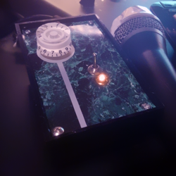
Funny and weird looking thing.
u92cWFz.png
 
RiffRalf said:
Do you guys have any recommendation on what I could do to lower the noise floor even future (other than swapping to a cleaner op amp) or is this as good as it gets? If so, I certainly don't complain.  :)

I would've started with a THAT 1512 or TI INA163 mic preamp chip instead of the 5532. Much lower noise, simpler gain configuration, and no need for matching resistors to ensure best CMRR.

As was noted elsewhere in this thread, the 5532 is the wrong choice for a high-gain low-noise input stage.
-a
 
Andy Peters said:
RiffRalf said:
Do you guys have any recommendation on what I could do to lower the noise floor even future (other than swapping to a cleaner op amp) or is this as good as it gets? If so, I certainly don't complain.  :)

I would've started with a THAT 1512 or TI INA163 mic preamp chip instead of the 5532. Much lower noise, simpler gain configuration, and no need for matching resistors to ensure best CMRR.

As was noted elsewhere in this thread, the 5532 is the wrong choice for a high-gain low-noise input stage.
-a

Thanks Andy, I will check those two out. Right now I actually use a LF353  since I haven't got any of my NE5532's to work at all, strange. Must have been flawed from the factory or something.
 
RiffRalf said:
Andy Peters said:
RiffRalf said:
Do you guys have any recommendation on what I could do to lower the noise floor even future (other than swapping to a cleaner op amp) or is this as good as it gets? If so, I certainly don't complain.  :)

I would've started with a THAT 1512 or TI INA163 mic preamp chip instead of the 5532. Much lower noise, simpler gain configuration, and no need for matching resistors to ensure best CMRR.

As was noted elsewhere in this thread, the 5532 is the wrong choice for a high-gain low-noise input stage.
-a

Thanks Andy, I will check those two out. Right now I actually use a LF353  since I haven't got any of my NE5532's to work at all, strange. Must have been flawed from the factory or something.
Back last century I did the math and a 5534 with a low Z mic (150 ohm) delivered about a 9 dB NF on paper (9dB more noise than theoretical noiseless preamp). A LF353 will be higher noise than that.  A dedicated mic preamp IC should deliver a NF between 1-2dB.  So a significant noise improvement. Back in the '70s I used a 5534 mic preamp in a DJ mixer kit, but used transformers for console preamps, until I found some really low noise transistors (late '70s) that could compete with transformers for noise performance.

I've seen general purpose op amp mic pre amps used in low fi fixed install products where noise floor is not a huge concern.  For recording several dB will matter.

JR
 
Back
Top