tube power supply turn on time

GroupDIY Audio Forum

Help Support GroupDIY Audio Forum:

This site may earn a commission from merchant affiliate links, including eBay, Amazon, and others.

Gus

Well-known member
Joined
Jun 3, 2004
Messages
5,269
Location
n
I have a question

What is the max surge current for long fil life for a 150Ma 6.3V heater. I have not found this in a book or site.

Some background on the question. Building tube microphones I have found some tubes work better than others. Most tubes were not designed for microphones. So when I find a good one I want to make last a long time.

I have a SIMPLE supply that limits the max current to about 260 ma with a cold heater. I can build stuff that is more complex but is this good enough?
 
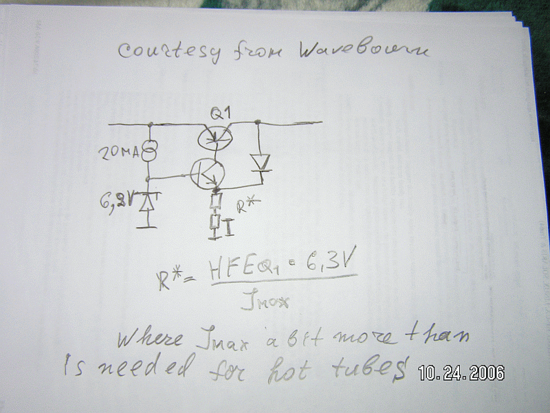
toobfilstart.gif
 
Wavebourn

Thanks for the schematic.

I have seen schematics of circuits like that. You need to test Q1 at operating current for Hfe. Looks like a constant current at a zener fixed voltage "feeding" the base of a PNP pass device. Max current is limited to base current X Hfe. Simple but depends on selection of a part(s) for the device used and how flat the Hfe vs Ic curve is.

I am not understanding the diode on the output why are you passing more current through the current setting resistor(s)

I am working with a supply circuit fragment DIY builders use.

My question was what I posted, max surge current.
 
[quote author="Gus"]Wavebourn

Thanks for the schematic.

I have seen schematics of circuits like that. You need to test Q1 at operating current for Hfe. Looks like a constant current at a zener fixed voltage "feeding" the base of a PNP pass device. Max current is limited to base current X Hfe. Simple but depends on selection of a part(s) for the device used and how flat the Hfe vs Ic curve is.

I am not understanding the diode on the output why are you passing more current through the current setting resistor(s)

I am working with a supply circuit fragment DIY builders use.

My question was what I posted, max surge current.[/quote]

The diode acts a clamp and prevents the output voltage from rising above 6.3V by stealing base drive from pass transistor.

A good thing about this circuit is that it requires almost no voltage overhead from the PS. While HFE changes with temp and sensitivity to device parameters of pass element may make initial current limit a trial and error exercise, this is probably OK for one off designs.

(edit) Or if set for a wide enough current limit band to only protect against gross overloads. (/edit)

JR
 
[quote author="Gus"]Wavebourn

Thanks for the schematic.

I have seen schematics of circuits like that. You need to test Q1 at operating current for Hfe. Looks like a constant current at a zener fixed voltage "feeding" the base of a PNP pass device. Max current is limited to base current X Hfe. Simple but depends on selection of a part(s) for the device used and how flat the Hfe vs Ic curve is.

I am not understanding the diode on the output why are you passing more current through the current setting resistor(s)

I am working with a supply circuit fragment DIY builders use.

My question was what I posted, max surge current.[/quote]

No, max current is limited by max emitter current (depends on resistor from emitter to ground). The point is, I always choose the maximal current a bit higher then needed for hot tube. They start slower, but the filament heats up more proportionaly in all parts, so the tube serves longer. However, lot of people disagree with me, they claim that they did not see tubes with broken filament, but saw them with too weak emission.

Diode in the output is a degenerated transistor in the opamp consisting on 3 transistors. Why diode, because base - emitter breakdown of transistors is low (however, in particular case of 6.3V only it is safe to use transistor).


Speaking of the different betas of different transistors, what's wrong in adjusting one trimmer if you anyway do a lot of soldering and other mechanical work? No need to select Hfe, no need to care about beta droop, just turn trimmer left, switch on power, see output voltage and slowly-slowly turn right the pot until it becomes 6.3V, after that turn right a little bit more.
 
[quote author="Wavebourn"][quote author="Gus"]Wavebourn

Thanks for the schematic.

I have seen schematics of circuits like that. You need to test Q1 at operating current for Hfe. Looks like a constant current at a zener fixed voltage "feeding" the base of a PNP pass device. Max current is limited to base current X Hfe. Simple but depends on selection of a part(s) for the device used and how flat the Hfe vs Ic curve is.

I am not understanding the diode on the output why are you passing more current through the current setting resistor(s)

I am working with a supply circuit fragment DIY builders use.

My question was what I posted, max surge current.[/quote]

No, max current is limited by max emitter current (depends on resistor from emitter to ground). The point is, I always choose the maximal current a bit higher then needed for hot tube. They start splowe, but the filament heats up more proportionaly in all parts, so the tube serves longer. However, lot of people disagree with me, they claim that they did not see tubes with broken filament, but saw them with too weak emission.

Diode in the output is a degenerated transistor in the opamp consisting on 3 transistors. Why diode, because base - emitter breakdown of transistors is low (however, in particular case of 6.3V only it is safe to use transistor).


Speaking of the different betas of different transistors, what's wrong in adjusting one trimmer if you anyway do a lot of soldering and other mechanical work?[/quote]

There are multiple issues with using trim pots. In a production environment it requires calibrated test equipment. Hooks or test points in the circuit for making the measurement, and an easy to follow well documented procedure for skilled (more expensive) workers to follow. Further the trim pot needs to be secured after setting so it doesn't shift from mechanical shock (glyptal, or nail polish), and hopefully the customer won't disturb factory settings.

There are even some unwritten rules about design for trim pots. Their common failure mode is wiper open, so in circuit that fault mode should not result in an extreme setting. A classic mistake in power amp design was to have the output stage class A current trim pot fail with max bias current not min, often taking the output stage with it. Likewise it is good practice to limit the range of adjustment so you can't ecncounter extreme conditions prior to adjustment.

I can't recall the last time I used a trim in a design. A few decades, but in 15 years at Peavey the economics of eliminating trims was very apparent and justified the effort. YMMV

JR
 
[quote author="JohnRoberts"]

There are multiple issues with using trim pots. In a production environment it requires calibrated test equipment. Hooks or test points in the circuit for making the measurement, and an easy to follow well documented procedure for skilled (more expensive) workers to follow. Further the trim pot needs to be secured after setting so it doesn't shift from mechanical shock (glyptal, or nail polish), and hopefully the customer won't disturb factory settings.

There are even some unwritten rules about design for trim pots. Their common failure mode is wiper open, so in circuit that fault mode should not result in an extreme setting. A classic mistake in power amp design was to have the output stage class A current trim pot fail with max bias current not min, often taking the output stage with it. Likewise it is good practice to limit the range of adjustment so you can't ecncounter extreme conditions prior to adjustment.

I can't recall the last time I used a trim in a design. A few decades, but in 15 years at Peavey the economics of eliminating trims was very apparent and justified the effort. YMMV

JR[/quote]

Agree, more complex design may be cheaper in mass production despite more elements are needed, from current sensing resistor to current amplifier.
 
Back
Top