U87 Ai circuit: how low/high can you go? (de-emphasis capacitors)

GroupDIY Audio Forum

Help Support GroupDIY Audio Forum:

This site may earn a commission from merchant affiliate links, including eBay, Amazon, and others.

stoa

New member
Joined
Sep 5, 2021
Messages
4
Location
Austria
Trying to use @mihi_fuchs's awesome adaption of the U87 Ai circuit with different capsules, I wonder how far we can safely deviate from the original feedback capacitor values?

So for the high-frequency roll-off, Neumann went from 220pF (C6) to 160pF (C105) in the U87A, which meant slightly more highs.
Has anyone tried significantly different values to accomodate, say, a CK12-style capsule?
Will, for example, 47pF just lead to virtually no roll-off? What do you guys think - how low can we go? Will there be any side effects?

Same goes for the (fixed) low-cut, which I think is an often neglected quality of the U87. (Not talking about the switchable low-frequency roll-off here.)
Neumann went from 33nF (C5) in the vintage U87 to 47 nF (C104) in the Ai, which meant slightly more bass.
Again, will, for example, 330pF just 'switch off' the low-cut? How far can we go? Any experience to guide me before soldering and measuring for hours? ;)

(I have a vague memory someone here might have simulated that in the past, but I can't find anything related.)

Thanks for any advice to the good people on this amazing forum!
Matthias
 
As much as you want, all is safe, find the one you like most with your capsule, headbasket, etc... 160pf is quite ok for any k67 capsule as a starting point. For edge capsules maybe 100pf would be enough, but edge capsules usually do not have same k67 low end, keep that in mind
 
It is not even a 'simulation', but a real measurement!
I'm having a hard time reproducing these results in simulation. Changes to c6 ("treble cap") simulate perfectly, but changes to c5 don't seem to have all that much effect (other than changing overall gain a bit and slightly decreasing low end - as in, a few tenth's of a dB less at 40Hz). Changing the value of c8/c107 (source resistor bypass cap) has a MUCH more pronounced effect on bass. A change from the usual 20uF to 3.3uF will cut almost 6dB at 40Hz! Also, an increase to 100uF will get you back about ¼ dB at 40Hz. I imagine there are a number of vintage U87's out there with leaky/drifting c8/c107 caps that have lost a lot of bass!

When you measured these changes, were they only measured though the 'Messing' calibration input, or were they actually measured though the capsule?
 
Yes, I injected the signal into the "Mess Eingang".
The effect of the source bypass capacitor is also influenced by the value of the source resistor.
My DIY remakes have an even better low-end response than an original U87ai!
 
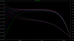
I am unable to replicate that in simulation. I wonder what the issue is. When I inject signal at the calibration input, I see the curves you mention (this is stepping the value of c5 from 33n to 330n):
Screenshot 2024-03-14 at 8.55.07 AM.png

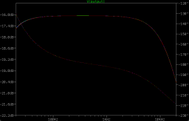
However, when I inject the same signal at the front diaphragm and step the same capacitor values, I see barely any change:
Screenshot 2024-03-14 at 8.56.07 AM.png

As I mentioned before, changes to c6 and c8 reflect perfectly through either input, so it's strange that I can't replicate your results.
 
However, when I inject the same signal at the front diaphragm

Can you also show us the schematic, how your signal source is connected? I've got a hunch that's where your issue is.

This sorta reminded me of a line of AvE's - "it works in practice... but does it work in theory?!???" :D
 
Can you also show us the schematic, how your signal source is connected? I've got a hunch that's where your issue is.

This sorta reminded me of a line of AvE's - "it works in practice... but does it work in theory?!???" :D
Happy to! If I'm making a silly mistake, I'd rather find out :)

This is set up for cardioid-only.

Signal going into front diaphragm:
Screenshot 2024-03-14 at 9.18.52 AM.png

Signal going into calibration input:
Screenshot 2024-03-14 at 9.21.18 AM.png
 
Hint: use AC amplitude as 1 (not 0.1), to get more realistic dB figures in those plots.
 
Hint: use AC amplitude as 1 (not 0.1), to get more realistic dB figures in those plots.
I'm not as interested in the absolute volume levels (those would depend on the volume of the source being recorded), but rather the level differences between frequencies.

I just tried it with AC amplitude = 1, and the results are the same: the stock 33nF capacitor results in -2.605dB down at 40Hz relative to 1kHz. Around 130nF makes the circuit essentially flat, and anything bigger than 130nF results in a slight bass-boost.
 

Latest posts

Back
Top