UA 1176 wrong value resistors

GroupDIY Audio Forum

Help Support GroupDIY Audio Forum:

This site may earn a commission from merchant affiliate links, including eBay, Amazon, and others.

SSLtech

Well-known member
Joined
Jun 3, 2004
Messages
5,447
Location
Florida (Previously UK)
Mr Winston O'Boogie made reference on several occasions to a wrong value resistor fitted at production in the (from memory) output stage of the 1176 reissues. -Anyone remember which it is? -He's vacuumed up all of his posts so I can't find the information anywhere.

Keith
 
half way down the page

http://66.249.93.104/search?q=cache:JuyUPTCAQh4J:www.groupdiy.com/forum/viewtopic.php%3Fp%3D7007%26sid%3D570aadc8bafa9a6327470333c954517a+site:www.groupdiy.com/forum+1176+resistor+winston&hl=en
 
no probs..
nothing recent (past few years) is ever lost (including most of the stuff from the old place)
Google cache will get it back most of the time...
 
I'm often puzzled by that... Google cache.

Other than the 'cached' tab after each return, is there a way to simply search all cached in the first place? -like cached.google.com or something?

Keith
 
..let me google that for you:

https://repforums.prosoundweb.com/index.php?topic=8998.0
and

https://groupdiy.com/threads/ua-1176-reissue-questions.21958/
the essence is:

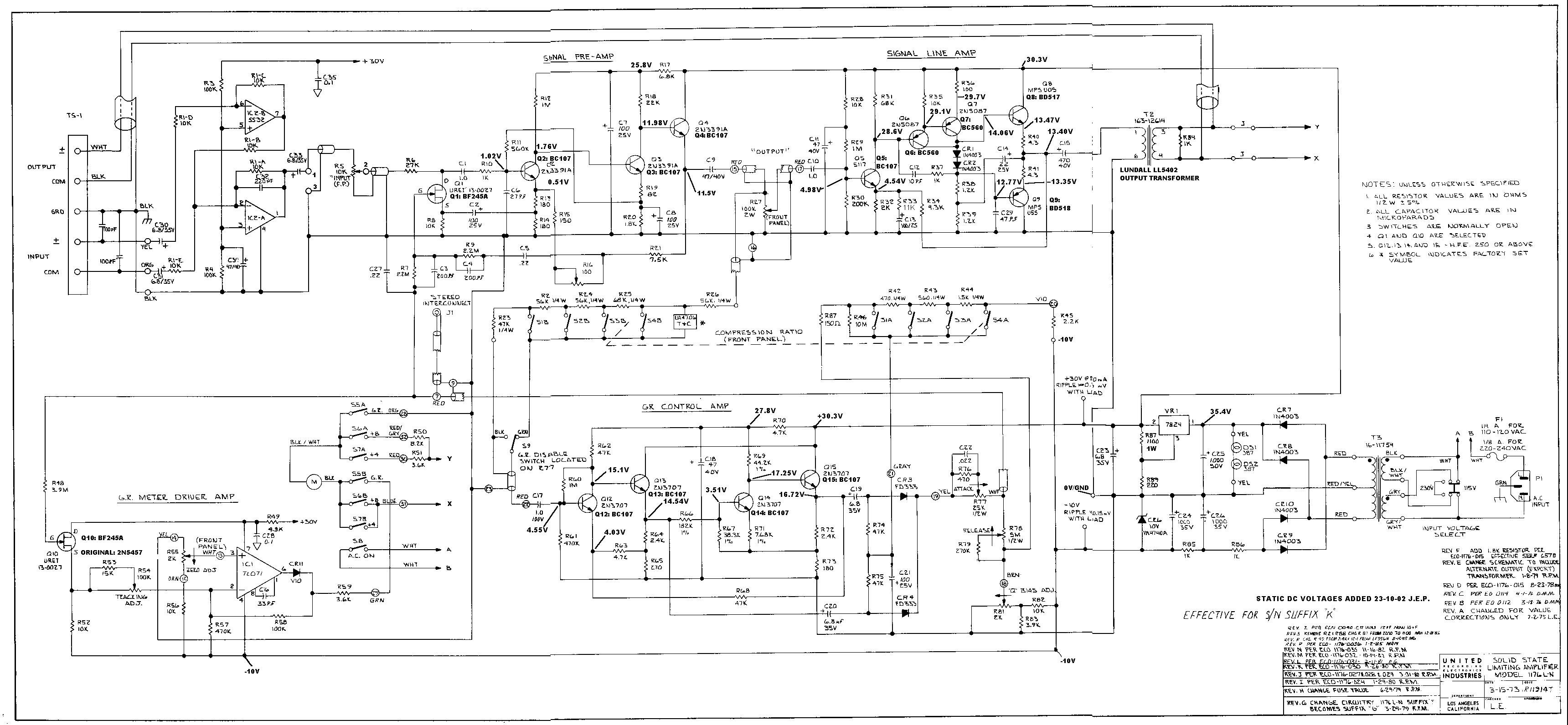
It was one of the pair of R's that biases up the base of Q4. Both resistors should be equal and are, in the 1176, supposed to be 2.7 Meg each. The top resistor was indeed 2.7 Meg but the bottom one was 270K! I checked the proto units that were on a special engineering shelf and all the parts were the correct value. I then checked the units that were being built and coming off the production line. All of them had the wrong 270K resistor installed. I checked the B.O.M. and, sure enough, that part was shown as a 270K on the production document but was accurate (2.7M) in the proto docs. I notified my, then, boss about it and after a meeting with his superiors it was decided to leave the incorrect part in place as it might change the sound from units that were already out in the field


/Jakob E.
 
I'm still trying to figure out which resistor they were talking about. Because there is a lot of versions to this schematic.
Also, I could see them changing the voltage divider for the stereo link part of the negative feedback to actually make that part of the circuit correct.

The first output transistor's base circuit is going to change depending on what transistor was used.
Even looking at your copy of suffix K (11th circuit redesign) I really don't fallow what they are talking about.

http://www.gyraf.dk/gy_pd/1176/1176sch.gif
1176sch.gif

On the symptom of the low audio when control is all the way to the left, The panel's input control's wiper is not reading 0 ohms when all the way left. So, change the control out with a better one.

On the designs that use the crappy balanced T attenuator on it its going to do that. Because its not a precision balanced attenuator and its not going to work well when its not fed by an output transformer from a previous device. You could I guess back the gain off by adjusting R16 But that will throw off other things too.
 
Last edited:
Rev's C,D and E ouput stages used the 2.7M Ohm resistors to bias the o/p stage.
After that, they changed the o/p stage and o/p transformer.
 
In the UA reissue I have. R12 is 1.8k.
In the Rev D it is 910 ohms.
It was changed to 1.8k in Rev F
 
Back
Top