Using a Microcontroller's A/D, problem with noise

GroupDIY Audio Forum

Help Support GroupDIY Audio Forum:

This site may earn a commission from merchant affiliate links, including eBay, Amazon, and others.

skrasms

Well-known member
Joined
Jun 16, 2004
Messages
72
Location
Gary/Purdue-Lafayette
It's been a long time since I've posted anything here, but I finally have time outside of class to work on my own designs. This is part of a synth module I'm working on. I'm taking a CV input for pitch (in the range of -3 to +7V), doing a little math to get the range I want between 0 and 5V, and feeding it into a microcontroller's A/D pin. In the opamp circuits, the math is working and gives all the right voltages. However, as soon as I connect the opamp output to the microcontroller's A/D pin, 0.4Vpp of noise suddenly shows up and ruins the results. I need to bring the noise down to 0.01V or lower, but I have not been able to attenuate it at all. I tried adding a buffer between the opamp output and A/D pin, but that did not help, nor did adding a simple RC filter with a low cutoff. I am at a loss because none of my usual fix-its are working here. I am grateful for any help, and won't hesitate to provide any additional information.

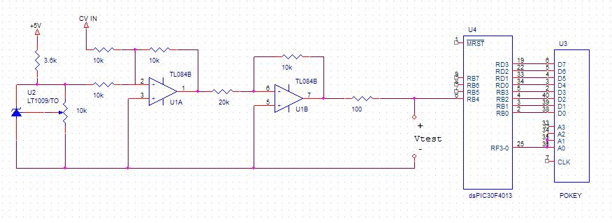
Here is a partial schematic. I would make it more complete, but I keep running into demo restrictions in OrCAD Capture. It shows the full analog chain, at least. The opamps are powered from a +/-12V supply, and the diode is to make a 2.5V reference.

schematic01.jpg
 
There may be some noise at the port inputs but should be less than one LSB. You are saying that the noise only happens when you connect the opamp output to the A/D input? If they are not connected, are both nodes clean?

I will assume all port tris bits, and and A/D configuration registers are set correctly.

In your voltage conditioning opamps to scale voltage to a useful range, are the opamp ground references tied directly to micro analog ground pins with nothing else sharing that run? If you are looking at this with a scope, where is the scope ground connected? Scope ground should be connect to micro AVSS also.

The micro A/D conversion is SAR and the internal reference string is presumably connected between AVSS (ground) and AVdd (plus supply), so input you deliver should be ground referenced to that same ground and clean relative to these voltages.

It might be useful to have a capacitor across U2, and all 3 "0V" grounds by opamps should be tied right to micro analog ground (AVSS).

JR

PS ground is never 0V :)
 
Try adding a 100-Ohm resistor between the opamp output and the ADC input.

While I am not familiar with the dsPIC, many microcontroller's ADCs have capacitive inputs. Driving a capacitor directly from an opamp (more precisely: adding unwanted phase lag to an opamp's negative feedback path) is a recipe for oscillation, which may account for the noise you're seeing.

Hope this helps,

JDB.
 
I always run a resistor and capacitor to the micro's A-D input. The input is indeed capacitive, and not only that, is more capacitive when the sample switch turns on. I usually use a 10k resistor and 0.01uF capacitor as a simple passive R-C filter but it also depends on the bandwidth you need. Also ensure that the PIC's power supply rails are adequately decoupled.

I would expect to see possibly 1 LSB of noise, though. Maybe less. It may not be a bad idea to implement a single-pole filter in software as that noise will disappear.

-Dale
 
Thank you for the responses so far!

I did not test the A/D pin by itself without input to see what its noise was. I will check that soon, but I do not have an oscilloscope handy (I lent mine to the student radio station here). I looked at the output of the opamp before and after directly connecting it to the A/D. The opamp output was clean until I wired it to the micro.

I put a 100 ohm resistor between the opamp output and ADC input as per the recommendation here, and it is definitely working better. Without a scope I do not know the specifics, but the pitch I'm getting out from the microcontroller is audibly more stable. What can I do to improve this further?

I had tried a passive RC filter between the opamp and micro previously, using 0.1uF and 1k, but it did not show any difference I could see in the scope output.

The grounding scheme/power is not at all ideal, but I am not sure how to improve it. Since this will eventually be a synth module, it will need to run from a single +/- 12 or 15 volt supply. Right now I am using a 5V supply and a +/-12V supply. The 5V will eventually need to be regulated off of the +12, but is not yet. The 5V is used for all the digital parts and as the signal to AVdd. I have both the +/-12 and 5V grounds tied together and serving as the ground for everything (even AVss). Ideally the analog and digital circuits would be isolated, but what can I do to improve the situation without sacrificing compatibility?
 
I found a 'scope to be not that useful to measure the last bit or two of A-D noise - just looking at the results was better. I always found too many artifacts on the scope due to grounding of the scope, or grounding on the board. Sometimes the A-D noise would triple by just connecting the ground lead of the scope probe!

As for power supply filtering, make sure you have as much decoupling as possible right close to the micro. If you have a separate voltage reference input or analogue power and ground pins, pay special attention there. Same goes for the little R-C filter. Try connecting the return of the capacitor directly from the analogue input pin to the A-D ground pin. Sometimes it takes a bit of experimentation in terms of grounding.

-Dale
 
[quote author="skrasms"]I did not test the A/D pin by itself without input to see what its noise was. I will check that soon, but I do not have an oscilloscope handy (I lent mine to the student radio station here). I looked at the output of the opamp before and after directly connecting it to the A/D. The opamp output was clean until I wired it to the micro. [/quote]

Here's a thought. You need a 'scope to verify this, but it's possible that your noise is only occurring while the ADC is converting; IOW an artifact of the conversion process. As long as the input is stable during the sampling time you're fine and it might not matter what it looks like while the converter is in hold/convert time. Configure a spare micro pin as an output and pull it high at the start of the conversion and use it as a 'scope trigger. Watch the ADC input on another 'scope input and see what happens around during the conversion cycle.

It's helpful if you have some way of logging your conversion results.

I put a 100 ohm resistor between the opamp output and ADC input as per the recommendation here, and it is definitely working better. Without a scope I do not know the specifics, but the pitch I'm getting out from the microcontroller is audibly more stable. What can I do to improve this further?

You haven't mentioned your construction techniques. Are you building this on a protoboard with a ground plane?

Also, you don't indicate any decoupling caps on your op-amp or your micro's supply pins. You need them.

100 pF (or whatever, depending on your bandwidth requirements) across the TL084 feedback resistors can help too.

The grounding scheme/power is not at all ideal, but I am not sure how to improve it. Since this will eventually be a synth module, it will need to run from a single +/- 12 or 15 volt supply. Right now I am using a 5V supply and a +/-12V supply. The 5V will eventually need to be regulated off of the +12, but is not yet. The 5V is used for all the digital parts and as the signal to AVdd.

You may see some improvement by providing two separate 5V regulators, one for the digital and one for the analog stuff that needs it.

I have both the +/-12 and 5V grounds tied together and serving as the ground for everything (even AVss). Ideally the analog and digital circuits would be isolated, but what can I do to improve the situation without sacrificing compatibility?

The grounds should all be the same, and ideally a plane. You want to keep the digital circuitry away from the analog stuff but the ground needs to be the same. See here, for example.

Good luck,

-a
 
On further experimentation, the 100 ohm resistor in series seems to be altering the output of the opamp circuit. That is, I'm ending up with different voltage scaling than I need and it is throwing off the synth tuning. How can I change the opamp circuit to compensate for this resistor, or is there an alternative way to prevent oscillation?

I am building the circuit on several breadboards at the moment. I do not have a single board large enough for all the parts. The grounds are connected so that each board's ground connects to the "middle" board's ground, making branches. I did that to avoid any ground loops.

The schematic I attached leaves out additional parts that I could not show because of various demo restrictions in Orcad. The micro, pokey, and opamp have bypass caps from Vcc to ground.
 
[quote author="skrasms"]On further experimentation, the 100 ohm resistor in series seems to be altering the output of the opamp circuit. That is, I'm ending up with different voltage scaling than I need and it is throwing off the synth tuning.[/quote]
Where exactly are you measuring? When exactly are you measuring? Does the 100R resistor between opamp and ADC change the voltage at the opamp output? Compared to what? The output of the opamp with no loading? The output of the opamp connected directly to the ADC? Please be more specific.

You may also want to go over the dsPIC's documentation (again). What is the input impedance of the ADC? What is the recommended ADC input buffer, as shown in the manufacturer's data sheet (or on a devkit either produced or approved by the manufacturer)?

Are you sure that you're driving the right pin? Are you sure that the ADC input pin isn't shorted to an adjacent (digital) pin? We've all been there. If you are using connectors or solderless breadboards, check the contacts. In my experience the majority of weird fault conditions is caused by connectors or other electromechanicals.

Good luck,

JDB.
 
I have some experience with the 10 bit A/Ds in the smaller Microchip parts and they aren't that hard to work with, while you do have to dot all your I's and cross your T's. Make sure nothing else is active on that port. Microchip often throws the kitchen sink into those parts so make sure there isn't an active pull up or something else going on with that particular I/O port.

I directly drive my A/D with a TL064 with no instability problems, but I do use feedback and PS caps.

The input impedance of such A/Ds are quite high and certainly not subject to forming a significant voltage divider with 100 ohms when properly set up. If anything the 100 ohms will form a pretty fast R/C with internal sample and hold, but as I recall there's already a finite R in the port switching, so I wouldn't expect a huge difference, and certainly not a DC error.

I would suggest confirming that your code is solid.

As I mentioned in my earlier post the TRIS bits and configuration registers must all be set properly.

The MCHP A/Ds require a certain acquisition time to get a stable sample, and will advise max conversion speed for full bit accuracy.

How often are you sampling that line? Do you leave everything set up and on and just ping the A/D or reinitialize every time. Are you sampling multiple ports or just that one?

I don't think you understand my comments about the ground integrity. For your purposes just think of it as a larger circuit node called ground, but that gets Vss, AVss, and sundry other sub ground nodes attached.

The opamp and voltage input needs to be referenced to AVss. The connection on the PCB or breadboard, or whatever should be a clean shot from opamps to AVss pin, AVss needs to connect to Vss, and Vss to power supply ground.

The advice to have a modest feedback capacitor on opamp will lower that opamp's output impedance at high frequency which may be useful.

Adding more resistance in series will impact acquisition time but if you are only doing that one conversion, it's not a concern. If you are scanning several inputs the aquisition time must be accounted for by using a short delay between setting up the port and taking a reading.

As others have offered, depending upon the rate of change you need, you can also take multiple a/d conversions and average the result to reduce noise, but this shouldn't be necessary starting with that much resolution.

JR
 
I should have stopped working earlier last night, after my cold medicine kicked in I was making all kinds of mistakes. Disregard my last post about the 100 ohm resistor throwing off the scaling. Today I setup several tests that I hope will make things clearer. I think my explanations so far have been pretty poor.

Starting with the software, I'm defining the pins/ports for this part as follows:
ADPCFG = 0x000F; //All AD Inputs on except B3-B0
TRISB = 0xFFF0;
Eventually there will be other pins sampled on the B port, but right now I am only sampling B4. B3-B0 are outputs for digital data.

The programming is all done in C, and I'm using mikroC's built in Adc_Read command. I believe it initializes all of the AD registers except ADPCFG every time it is called. It is supposed to take care of proper acquisition and conversion time. Once the 12-bit value is sampled, it goes through math leading to the microcontroller sending out pitch data to a Pokey (an old Atari sound chip). The code after the sampling has all been thoroughly tested to work. The following chart shows some results from testing the micro code. The frequency of the Pokey output was measured with a Fluke 8060A.


digital.jpg


The outfreq(n) and Measured Frequency columns are both of the Pokey output. The outfreq(n) column was testing the accuracy of the code in writing a frequency directly to the Pokey. The Measured Frequency column was the resulting frequency after loading a given 12-Bit value into the math engine.

For testing the analog circuit, I set it up like this:


schematic02.jpg


analog.jpg


I sent CV into the circuit for several octaves of A, calculating the ideal voltage for each case. The voltage to the A/D was measured where it is marked in the schematic. I then plugged each measured value into a simulation of the math engine to get a predicted frequency output. The actual frequency out of the Pokey was then checked for each case. There is a large discrepancy between the measured frequency in this case and both the predicted/theoretical values.

The data sheet for the dsPIC I am using is here. The A/D information starts on page 127 in the pdf. I have not been able to find any kind of recommended ADC input buffer.
 
What is the actual 12-bit result (direct from the A-D converter) from each voltage test? One thing to check is that you don't get unintended rounding in the software. That can happen very easily.
 
Looks like minor gain/offset problem in DC level shifting front end

But lower than target input voltage making higher than target output frequency suggests multiple errors.

Frequency out is high at top and bottom.

You need to divide and conquer.. On analog front end you may need more precision resistors and/or trim.

Inside the micro look at how A/D input maps out to 12 bit digital result, then how that 12 bit data maps out to Hz.

Looks like a ton of fun...

JR
 
[quote author="JohnRoberts"]
Inside the micro look at how A/D input maps out to 12 bit digital result, then how that 12 bit data maps out to Hz.

[/quote]

Just to clear this up, the mapping from 12-bit data to Hz is in the first table I posted. Each of those values was put into the code in place of the data sampling block, and the resulting output is in the "Measured Frequency" column. I did this test to make sure rounding was not causing problems.

I do not have a map of A/D inputs to 12-bit data yet, but hopefully I can do that later tonight or tomorrow.

The error in the analog voltage seems negligible compared to that in predicted vs. measured frequencies.
 
OK, I follow, those 12 bit values are out of 4096 total codes, and that is spread over 5V for your target input voltage, and already tested.

Agreed looks like errors in A/D conversion.

Good luck.

JR
 
[quote author="JohnRoberts"]OK, I follow, those 12 bit values are out of 4096 total codes, and that is spread over 5V for your target input voltage, and already tested.

Agreed looks like errors in A/D conversion.

Good luck.

JR[/quote]

errors are much higher than LSB (which is around 1mV). Errors in second
table look like gain/DC errors.

BTW either I'm complete idiot or you have mapped -3V to 7V range into
-0.5 to 4.5 range, not 0 to 5. If this is 1V/octave system you are loosing parts
of top and bottom octaves, not much to worry about.

First thing skrasms, I'm utterly confused: do you have reading errors,
or noise at ADC input or detoriation of precision when you connect 084 to
ADC input?

Second thing, with 1% resistors you can throw away 12 bit precision.
So either go stupid and use trimmers or solder everything and calibrate
your mapping tables with precision voltage source at CV input. You
loose half LSB of precision at worst.

To determine if you have noise at ADC input do several consecutive
measurements. If results vary more than ADC error (which I will assume
to be half LSB), than you have either noise or bad ADC.

Third thing: grounding. AVss lead should not conduct significant currents.
Especially not switching currents from MCU core. Take separete wire
from AVss and connect directly to star ground point.
If noise is EM coupled than you are in a bit bigger problem.

BTW recomendation for ADC input buffer: to have less than 2K5
output impedance

cheerz
urosh
 
[quote author="recnsci"]

BTW either I'm complete idiot or you have mapped -3V to 7V range into
-0.5 to 4.5 range, not 0 to 5. If this is 1V/octave system you are loosing parts
of top and bottom octaves, not much to worry about.

First thing skrasms, I'm utterly confused: do you have reading errors,
or noise at ADC input or detoriation of precision when you connect 084 to
ADC input?

Second thing, with 1% resistors you can throw away 12 bit precision.
So either go stupid and use trimmers or solder everything and calibrate
your mapping tables with precision voltage source at CV input. You
loose half LSB of precision at worst.

To determine if you have noise at ADC input do several consecutive
measurements. If results vary more than ADC error (which I will assume
to be half LSB), than you have either noise or bad ADC.

Third thing: grounding. AVss lead should not conduct significant currents.
Especially not switching currents from MCU core. Take separete wire
from AVss and connect directly to star ground point.
If noise is EM coupled than you are in a bit bigger problem.

BTW recomendation for ADC input buffer: to have less than 2K5
output impedance

cheerz
urosh[/quote]

The mapping was set up to go -0.5 to 4.5 on purpose.
The Pokey cannot cover the full frequency range that midi supports, specifically in the low end, so cutting off the 0.5V is not a real loss. The mapping also made the math and design simpler in my mind with the components I have available. :grin:

Sorry about the confusion, I have been sort of grouping several problems together. The initial problem when I hooked up the circuit was that the pitch coming out was wobbling a lot and did not stay in tune across octaves as I "played" a midi-to-CV into it. At that point I connected a scope to the A/D input pin and saw about 0.4Vpp of noise. Disconnecting the A/D pin from the opamp and checking the opamp output voltage showed negligible noise.

After adding the 100ohm resistor between the A/D pin and the opamp output it sounds better in terms of wobbling, but is still going out of tune across octaves.

I am going to try some changes with the grounding/power scheme and see what happens, in addition to getting a mapping of A/D input vs. sampling results.
 
[quote author="bcarso"]Can you describe what the (0.4V!) noise looked like?[/quote]

It looked like very high frequency bursts of noise. Like miniature bursts recurring somewhere in the MHz range. As soon as I get my scope back I will post a picture. It still shows up even after putting decoupling caps on the power rails at every IC.
 
THis has been mentioned, but now you might just be dealing with sensor jitter, and in that case, you'll probably want to use some sort of averaging (also known as smoothing) algorthym.

http://www.arduino.cc/en/Tutorial/Smoothing


Smoothing

Reads repeatedly from an analog input, calculating a running average and printing it to the computer. Demonstrates the use of arrays.


Circuit
Potentiometer on analog input pin 0.


Code
// Define the number of samples to keep track of. The higher the number,
// the more the readings will be smoothed, but the slower the output will
// respond to the input. Using a #define rather than a normal variable lets
// use this value to determine the size of the readings array.
#define NUMREADINGS 10

int readings[NUMREADINGS]; // the readings from the analog input
int index = 0; // the index of the current reading
int total = 0; // the running total
int average = 0; // the average

int inputPin = 0;

void setup()
{
Serial.begin(9600); // initialize serial communication with computer
for (int i = 0; i < NUMREADINGS; i++)
readings = 0; // initialize all the readings to 0
}

void loop()
{
total -= readings[index]; // subtract the last reading
readings[index] = analogRead(inputPin); // read from the sensor
total += readings[index]; // add the reading to the total
index = (index + 1); // advance to the next index

if (index >= NUMREADINGS) // if we're at the end of the array...
index = 0; // ...wrap around to the beginning

average = total / NUMREADINGS; // calculate the average
Serial.println(average); // send it to the computer (as ASCII digits)
}
 
Back
Top