Using a Microcontroller's A/D, problem with noise

GroupDIY Audio Forum

Help Support GroupDIY Audio Forum:

This site may earn a commission from merchant affiliate links, including eBay, Amazon, and others.
I did testing of the A/D today. I used the same test circuit as before, reading the voltage directly from the A/D pin.

table03.jpg


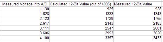
The first column is the voltage read from the A/D pin using my Fluke, and the second column is corresponding digital values calculated from mapping 0-5V to 0-4095. The last column is the data written into the micro from the A/D. What could be causing the nonlinearity in conversion?

For each value tested I watched at least a hundred samples to see how much noise was in the resulting data. Nothing varied by more than a toggling of the least significant bit.
 
It looks as though the reference voltages (mostly the upper one) is slightly lower than 5V. Check the tolerance of the voltage reference if you are using an internal bandgap reference, or check the value of the 5V supply at the Vref+ pin. Remember that the A-D converter is ratiometric to the reference voltage so if the +5 volt supply is really 4.88 volts, the readings are close to expected.

One 'out' is to use an A-D channel to measure a reference voltage and use that as a correction factor. At 5.000 volts, a 2.500 volt reference should read 2048 counts. If it reads 2098 counts, the +5 volt rail is actually at 4.88 volts and you can scale your output by multiplying by 2048 / 2098. Watch the precision of the multiply so you don't overflow or underflow. I would avoid trying to calibrate the +5 volt rail as that will change slightly with power supply loading and voltage regulator temperature. Voltage regs are usually only spec'ed to +/- 2% and that's at a specific load.
 
[quote author="dale116dot7"]It looks as though the reference voltages (mostly the upper one) is slightly lower than 5V. Check the tolerance of the voltage reference if you are using an internal bandgap reference, or check the value of the 5V supply at the Vref+ pin. Remember that the A-D converter is ratiometric to the reference voltage so if the +5 volt supply is really 4.88 volts, the readings are close to expected.

One 'out' is to use an A-D channel to measure a reference voltage and use that as a correction factor. At 5.000 volts, a 2.500 volt reference should read 2048 counts. If it reads 2098 counts, the +5 volt rail is actually at 4.88 volts and you can scale your output by multiplying by 2048 / 2098. Watch the precision of the multiply so you don't overflow or underflow. I would avoid trying to calibrate the +5 volt rail as that will change slightly with power supply loading and voltage regulator temperature. Voltage regs are usually only spec'ed to +/- 2% and that's at a specific load.[/quote]

Well that's embarrassing, I did not even think to check the 5V rail :oops:
It measured 4.88 volts, and swapping out with a new power supply that gives me 5.04V is already an audible improvement. So the conversion was linear, just not with the slope I was expecting.

Scaling based on 2.5V sounds very useful, thank you for that solution. Is the LT1009 circuit I am using now a good voltage reference? I have never used a voltage reference before, so I went with the only method I knew.
 
Does the uC A/D allow for an external reference?

Often system issues with different voltage refs can be remarkably improved by using one voltage ref for "all" of the different required voltages. That's to say, your source has a ref of its own somewhere. if you can enlist that to drive your analog processing and also the A/D (suitably scaled) you may get something that works very well indeed.

This isn't always feasible though, since you may not be able to access the source's ref.
 
Microchip's A/D modules allow you to externally access the two endpoints of the resistor reference string. These can be brought out on two package pins/ports and externally set to arbitrary voltages. The typical internal connection is to A(nalog)Vdd and A(nalog)Vss. The data sheet advises adding an external RC filter to reference string for very high sampling rates (200ksps).

For minor tweaks you could probably run AVDD and AVSS at slightly different voltages than digital Vdd and Vss. This would avoid tying up two I/O pins on the package but I wouldn't try pushing such a supply difference more than hundreds of mV. The data sheet suggests keeping supplies within 300 mV of each other.

While A/D is monotonic I wouldn't put too much faith into LSB accuracy.

JR
 
I am really thankful for all this advice. There is always so much to learn!

So for power and reference, would it be best to use a generic regulator to get the +5 for running the micro, but a more accurate 5.0V diode to get the voltage for AVdd? The voltage references I need are 5.0 for the A/D converter, and 2.5 for the analog circuits (used in a couple different spots). If I use a diode to get a 5V reference, is it enough to setup the 2.5V reference from that using a simple voltage divider?

I think that sounds a little confusing, so I'll try to put up a schematic tonight of what I am talking about.
 
#1: You could configure the A/D to use external reference and run the A/D 0-2.5V full scale.

#2: Using a precision opamp and precision resistors scale the 2.5V reference up to 5V for AVdd. Note: Vdd must be within 300 mV of AVdd.

#3: Adding a transistor buffer to #2 make your own precision 5V supply.

#4: Using a variable 3 term regulator, adjust +5V to be 5.0V. If VR reference is accurate enough you may be able to get close enough to 5.0V with precision resistors.

#5: Combine #2 and #4 for well behaved VR without need to trim.

#6: Feed the 2.5V reference into an unused A/D input and write a routine that runs at start up, or periodically, to measure that voltage and generate a scale factor to correct readings for actual PS voltage.

If this is a one off design #4 may be best option, and once you have a trimmed 5V rail, you may not need 2.5V ref in addition.

For production design avoid trims and go with one of the other options.

JR
 
Back
Top