Using polarization voltage to pad signal in Royer tube mod...?

GroupDIY Audio Forum

Help Support GroupDIY Audio Forum:

This site may earn a commission from merchant affiliate links, including eBay, Amazon, and others.

rascalseven

Well-known member
Joined
Jun 3, 2004
Messages
906
Location
"Tejas"
Hello,

I'd like to make a -10 or -15dB pad for a mic I built using the Royer tube mod:

RoyMic.png


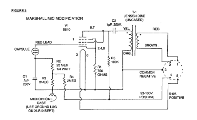
Which resistor sets the polarization voltage?  It appears that R4 and R3 form a voltage divider, so one or both of these should be switched to alter the voltage seen at the capsule.  How would I go about determining what values I need to accomplish a pad of a specific dB value?

Would be tremendously grateful for some direction for this.

Thanks so much!

JC
 
Should be R3/(R3+R4) * HT for the polarisation voltage. Output will drop roughly 6dB every time you halve that voltage.

Eg. 3/5 * 100V = 60V.

Lowering R3 lowers polarisation voltage. I'd look at other designs though; there may be a preferable solution.
 
Thanks for that!

As for the preferable solution, the only other way I know to pad is a capacitor in parallel with the capsule, though I'm a bit concerned about it being such a high impedance circuit. 

Plus I don't know the math for figuring a pad with such a capacitor.  I'm certainly open to anything that would work well.  The only other mic circuit I've done a pad for is a modified Oktava MK319 which allowed a switch to drop in a resistor to complete a simple voltage divider for the polarization voltage.  Works quite well, so that was the approach I wanted to take here, but this circuit doesn't allow for such a simple solution.

Do you prefer the capacitor in parallel route?  How would I determine the value of it?

Thanks as always.

JC
 
Reducing the bias voltage increases the relative noise and changes the frequency response of the capsule because of the electrostatic pull stretches the diaphragm less. It increases somewhat the max SPL handling.
The parallel cap also increases relative noise, but less, and add some distortion.
Why do you want to attenuate? Are you experiencing distortion from the head amp, or is it the preamp which distorts?
 
Would a different ratio transformer be an idea or am I talkin crap........
 
I'm not really experiencing problems.  I just finished the mic, and it sounds quite stellar (EQU47 body, Thiersch redline capsule, Oliver's T47 transformer, Royer circuit), I was just thinking I might run into problems at some point, but in reality don't really know when that would be.  I've already given it cardioid/omni switchability, so I may just leave it at that and not worry about a pad.

If I run into trouble later I can always add it then.

Thanks!

JC
 
What ARDE said.

Gary, that will work to reduce gain, but not at an ideal point; it doesn't stop the valve stage from clipping. Also, it affects the way the valve interacts with the transformer (might change LF frequency response marginally).
 
I think Royer decided there was sufficient grid leakage. It's also this side-effect which he used to polarise the CF design he released.
 
Thanks Roddy great info here fellas......just ordered a 5840 tube to make this circuit n try it with decent LD capsule cant wait.....
 
Back
Top