


Looking back at the feedback issue discussed by CJ and ruffrecords here:-
http://groupdiy.com/index.php?topic=59609.msg757475#msg757475
CJ said the tone changed because of the 50uF cap, but Ian disagreed.
I have just made this circuit and when I checked the frequency response, it does indeed change with different gain settings and I think I know why, here's the circuit for reference:-
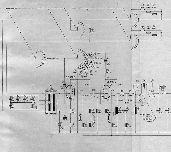
Ignore all the circuit after the 400H output choke as it's not relevant. The resistor string on the gain switch adds up to 70k and that is the load to ground on V2. The 50uF cap P13 acts like the wiper on this 70k "Pot" and sends the selected signal back to the V1 cathode resistor as +ve feedback (acts like -ve with respect to grid). the reactance of the cap is 170 ohms at 20Hz and 17ohms at 200Hz so its effect on the feedback string is negligible as the lowest resistance it encounters is 40k in the lowest gain settings.
However, when we look at its other function, that of a variable cathode bypass, we can see that its reactance is greater than the 98 ohms resistor at the maximum gain setting and almost equal at the second highest setting at 20Hz, so gain in the bass on the higher gain settings is relatively lower than mids and highs and the frequency response is impaired. Now this pre was used with bass filters in its intended TV studio role so maybe it was not an issue. but for those of us who want 20~20kHz studio roles then we need to put a much bigger cap in place than 50uF, more like 470 -1000uF I guess.
best
DaveP