Voltage-to-power amplifier

GroupDIY Audio Forum

Help Support GroupDIY Audio Forum:

This site may earn a commission from merchant affiliate links, including eBay, Amazon, and others.

Quince

Well-known member
Joined
May 31, 2006
Messages
68
Location
Vancouver, BC, Canada
Referring to the diagrams on the right side:
http://www.tubecad.com/email_2001/e0829/page4.html
I'm not sure how that circuit is actually mutiplying the voltage and current samples for feedback. Can someone explain it?
 
There's no multiplication going on. The author is confused---note the language: "...effectively [my emphasis] multiplied against each other..." I think I saw this some time ago and was tempted to write a letter of correction.

But by a combination of current and voltage feedback you can synthesize an output impedance, and at one matched to the load do a passable approximation to a power-regulated output, without dissipating a lot of power in a resistor and requiring a substantially higher voltage source. Note that the author's example circuit with values for "R" and "RL" is a poor one, since there's as much power dissipated in the current sense R as in the stated load R.

Someone in audioXpress a while ago suggested a filament supply using a simple change in the resistive network around a 317, and claimed that it regulated power. I was dubious when I saw no multiplier in the circuit, but after some study was surprised that it worked as well as it does for load R variations. It isn't perfect, but it's way better than I expected.

EDIT: Revisiting the circuit from tubecad in sim, I'm not sure what is really going on. The behavior is decidedly not that of a synthesized output resistance, and variations in load resistance cause wild swings in output power (20mW into 0.5 and 2 ohm loads for 100mV peak sinusoid in, and 51.4kW (!) for a 1 ohm load). The gain is highly variable with the output load, basically: about unity gain for the 0.5 and 2 ohm loads, and about +67 dB for 1 ohm. And for a given load the power into the load goes as expected as the square of the voltage.

Maybe there is a sign wrong on one of the opamp inputs.
 
I've not seen any multiplier circuits that are high accuracy. Even expensive ICs like MPY634 do only about a percent accuracy. Short of ADC->digital multiplier->DAC (which is likely to have too much delay to be useful), what's the most accurate multiplying circuit you guys are aware of?
 
A good fast ADC (successive-approximation, not sigma-delta) coupled to a good fast four-quadrant multiplying DAC (again, not sigma-delta) would probably be a reasonable approach with acceptably low delay. Won't be cheap though.

All of this is predicated on wanting to do this to begin with though---after all, the vast majority of speakers are developed using voltage sources. Until you persuade the speaker and transducer designers to use a different sort of source I'm not sure of the utility of a different sort of amplifier.

Of course integrated amp-speaker systems are another story.
 
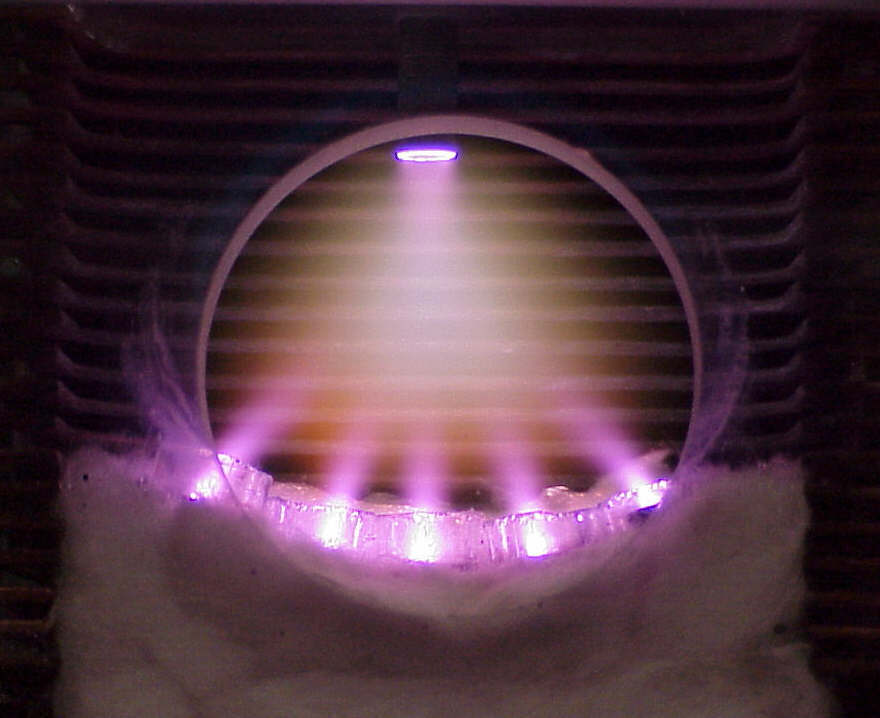
No, I need it for my plasma speakers; the design is a derivative of Hill's Plasmatronic speakers (see US patent 4,219,705). In Hill's case, the glow discharge was constant voltage, so a transconductance output stage was fine. In my case, I'm using a special electrode configuration in order to create stable plasma without the need for helium (the Plasmatronics needed a refillable helium tank) that results in a discharge with a complex I-V curve. The instantaneous delta-pressure created by the discharge is directly proportional (well, approximately, but to a high precision) to the instantaneous power input change to the plasma. That means I need power output. Unless, that is, I can find some other way to compensate for the I-V nonlinearity, which assumes I can measure it exactly and do predistortion.
This far I've not done any measurement; I'm assuming the specific I-V response based on various papers about the specific electrode configuration (microhollow cathode-sustained glow discharge). I only have a DC discharge at the moment and have yet to do audio-frequency modulation. Note that all this is quite different from the corona-type ionic tweeters that were most common (and still used by Acapella), so cannot be compared.

[Edit:] AD534L is 0.25% total error before trimming, but it costs $80...
 
Gas discharge devices are notoriously difficult load lines. One of my first pieces of instrumentation was a power supply for hollow-cathode reference lamps for spectroscopy, and I approached it using a current sense resistor as part of the loop. It was hell to compensate. Later I did one with a high-voltage transistor as a common-base stage driven by another low-voltage part and things worked much better.

A friend had to make a CO2 laser supply, and its load line was so foul he ended up just putting a lot of series R in to make it tractable. It was a formidable beast for a physics lab, a current source of a few hundred mA with about a 20kV compliance. He appeared one night at the door of my office after it had nearly killed him, looking much like Wiley E. Coyote after one of his many mishaps with one of the Acme products.

I think you have your work cut out.
 
I'm using microhollow cathode discharges as electron sources for the main discharge. So I have three electrodes -- two for the MHCD and a third anode. I initially tried copper/mica sandwitch for the MHCD, but that would erode pretty quickly. I got some sapphire wafer as free samples from a manufacturer and also platinum-plated some tungsten, and that seems to have solved the problem (platinum wire can be electrolytically dissolved in HCl, and that used for plating). I biased the upper MHCD electrode with resistors. Unlike corona discharges, it's absolutely silent (power supply ripple is below what I can measure at this voltage with my resistive divider, about 100 mV at the 2500 V DC the old supply was doing). I intend to have five MHCDs in an arc, for one main anode, per channel (Hill's patent explains the need for that shape). My old transformer was a modified MOT but it had huge leakage inductance and not enough power; I intend to rewind a 2 kVA transformer I have around when I have time. Also, the platinum plating rubs off pretty easily from the tungsten. I read a patent that suggests baking platinum-plated metal at high temperature under an intert atmosphere to diffuse the plating into the surface of the substrate; I can do that by sealing the electrodes in quartz-glass tube (such as from halogen light bulb) since that can withstand the needed temperature, but I've yet to get an oxy-acetylene torch as my propane torch won't melt quartz glass.
I didn't really smell ozone in my experiments. I am worried about UV, however, and I've no idea how to deal with that. The Plasmatronics were crossed over at 1 kHz though I know one person who managed 700 Hz; I'm using a good deal more power so I'm hoping around 500 Hz should be good. But I have no idea what the discharge's AC characteristics are yet, so haven't thought much about the amplifier. I've acquired a pair of forced-air cooled ceramic transmitter tetrodes that should be good for the output stage.
 
Certainly sounds like a heroic effort.

If you're not smelling ozone then you can't have all that much UV I should think.

One sense I have: I wouldn't worry too much about errors in multipliers until you get data on the actual nonlinearities inherent in the transducer. To say, at this point, that a power-linearly-proportional-to-voltage amplifier is optimal sounds like first-order theory talking. It may be a good approximation to start with, but if you're attempting some super-low-distortion system you will probably end up fitting all sorts of complicated predistortions, and when you do they can take out multiplier errors in stride. Beware of slow thermals.
 
Hey, looks like archive.org has an old copy of the now-gone site with measurements that a Plasmatronic owner took, and a photo:

Plasma chamber (window maybe 1.5 cm); preheated helium comes from the five cathodes/pipes at the bottom:

Plasmacell1.jpg


Phase and frequency response:

PL7.gif


Waterfall plot and step response:

PL7w.gif

PL7-step.gif


Looks like crossed at 500 Hz.
 
Back
Top