Voltage Tripler Questions - V Regs R1,R2 and Ripple

GroupDIY Audio Forum

Help Support GroupDIY Audio Forum:

This site may earn a commission from merchant affiliate links, including eBay, Amazon, and others.

guavatone

Well-known member
Joined
May 21, 2005
Messages
1,609
Location
USA
I have been seeing various permutations of Voltage triplers and I just wanted to make sure this is right before I waste some copper.

the one strange thing is the ground to chassis connection.  I am wondering if I should link C11 and C12 neg terminals, which is how I had it originally, but it didn't make sense to have one side of the pwr xfmr going to chassis gnd.

also, can I get away with 50V caps on C10 and C11?

:?

trip1.png
 
I'm a bit of a voltage tippler myself. occasionally imbibing at times, always wishing I could just quit cold turkey and never go back. Never stay off the wagon as long as I wish. But I never really hit the hard stuff either, no more than 240 AC or ~600DC

:wink:
 
You do need to connect the negative terminal of C11 and the transformer to ground. This is probably considered a "half wave" tripler. 50V caps should be okay for C10 and C11.
 
thanks burdij. I was also wondering what is best for filtering after the tripler. C12 is part of the tripler circuit, but I just raised the capacitance figuring that C12 can serve as a filter cap as well. Does that seem like the way to go?
 
C12 is like a bucket with a hole in it. The tripler is bringing smaller buckets of electrons up to the top and dumping them in. Depending on how much current you are planning on drawing out of the bucket, the size of C12 will affect how much the bucket can leak before the voltage drops below the regulator dropout margin. At that point, the servo mechanism no longer has enough voltage to prevent the output from sagging. This is when the line noise will become apparent. As long as the input voltage minus the output voltage is above the margin, the output noise level will only be affected by the noise sources in the regulator.

One thing you might consider doing is making the size of the capacitor C14 much smaller. This capacitor is going to damp the feedback in the servo loop. If the damping time constant is below 60 Hz the regulator will not be able to correct for line noise fast enough. I usually use a small value cap, like .1 uf or so at that point just to prevent high frequency noise components from appearing in the output.
 
Your textbox in the upper left about jumper settings for primary voltages look mixed up. You want the primaries in series for 230VAC and in parallel for 110VAC operation.
R6 at 220k looks pointless as R5 at 120R is already pulling 10.4mA for the required min.load of U2.
With R5 at 120R your trimmer VR2 would be set to ~4k5. This will heat up to 0.5W, more than most trimmers can stand.
You might consider splitting VR2 into a fixed 3k9/1W and a 1k trimmer in series, allowing for adjustable range closer to your target voltage, varying from 42VDC to 53VDC. YMMV.
 
[quote author="burdij"]
One thing you might consider doing is making the size of the capacitor C14 much smaller. This capacitor is going to damp the feedback in the servo loop. If the damping time constant is below 60 Hz the regulator will not be able to correct for line noise fast enough. I usually use a small value cap, like .1 uf or so at that point just to prevent high frequency noise components from appearing in the output.[/quote]

I'd expect this to show up as poorer line regulation, but I don't see that in plots of such with and without the 10uF in the datasheet. See for example http://cache.national.com/ds/LM/LM117.pdf , page 7.
 
thanks for catching that harpo. I was having quite a time setting up the jumpers on my layout correctly that I mixed that up.

I haven't seen an equation for R1/R2 Wattage. do you know if one exists?
 
[quote author="guavatone"]I haven't seen an equation for R1/R2 Wattage. do you know if one exists?[/quote]
Ohm's law?
(R1/R2 changed to your parts labeling R5/VR2)
Regulator reference voltage/R5=1.25V/120R=10.4mA; 1.25V*0.0104A=0.013W
(Target voltage - reference voltage)/VR2=(48-1.25)/4k488=same current as above; 46.75V*0.0104A=0.49W.
 
Thanks Harpo, I missed the obvious. Now I have a proper calculator for adj regs. I them played with new values and came up with R5=240R giving under 1/4W. Ideally I think I want VR2 to have a series 8k2 and 1-2k trimmer.

As far as the servo mechanism, would the new RC filter help? Can I just bypass C14 with a 100n poly to help?

new mod

trip2.png


BTW, on the 317 datasheets they say they are using a 240R R1 and the schems have 120R :?
 
[quote author="guavatone"].., would the new RC filter help? Can I just bypass C14 with a 100n poly to help?

new mod

trip2.png


BTW, on the 317 datasheets they say they are using a 240R R1 and the schems have 120R :?[/quote]
If you are refering to National's part, they show examples of different regulators in no particular order (LM117/LM317) with different min.load requirement.
Looking at datasheets of National/OnSemi/SGS Thomson/TI/Vishay, these all seem to have 10mA as worst case min.load, only exceeded by Fairchild at 12mA, there may be other.
Your choice of R values (8k2+1k trim)/240R and additional load R6 at 6k8 should meet these worst case specs.

Your RC filter should help, but value of R1 (470R) depends on raw DC voltage after your tripler circuit and your current load, you never mentioned.
Not shure, if bypassing C14 will help. According to National's datasheet, C14 should help ripple rejection, but Reg.adj. will have to see any errors to regulate them, so smoothing these may be contraproductive. (similar TL783 datasheet says, adjustment-terminal capacitors are not recommended because they can seriously degrade load transient response) In the past I wasn't that lucky in using C14 at all, maybe only some bad batches of caps. Try it and see.

Just curious, is there any special reason using a 10-0-10VAC transformer with a tripler behind?
If only needed for phantom, a 40VAC rectified and smoothed or a 22VAC with Villard- or Cockroft-Walton multiplier will probably give you less ripple.
 
There is an odd discrepancy then between the quoted 783 prescription for good load transient response and what National shows for the behavior of the 117 (note that I went back and edited the link in my earlier post which didn't work with a comma appended).

National shows superior load response when the reference cap is used.

I guess someone should actually make some measurements.
 
I am using a tripler because I am working my way up to one of these:

http://www.celnav.de/hv/hv3.htm
:wink:
multiplier120kv1.jpg

so i can do this:
spark90kv.jpg


Actually I am using a tripler because I have a bunch of these xfmr's. This is only going to be pulling 10-25 mA since it will only be for 2 mics at most for now. I feel a bit silly bothering folks about a circuit that is not all that important, but I am curious about some things about these regs that I didn't understand up until now.

I was trying to figure the reasoning of different R1/R2 values. I read somewhere that the minimum current from output to Adj was (R1) 10mA on the spec sheet but that down to 5mA was fine.

is this the spec sheet rating?
Adjustment Pin Current Change = 10 mA ≤ IOUT ≤ IMAX

does this mean that the current from R1 just needs to be less than 10mA than Iout?

This guy has some wacky results with adj bypass and no output caps, check his his final tests.

http://www.tnt-audio.com/clinica/regulators_noise2_e.html
 
[quote author="guavatone"]Actually I am using a tripler because I have a bunch of these xfmr's. This is only going to be pulling 10-25 mA since it will only be for 2 mics at most for now. I feel a bit silly bothering folks about a circuit that is not all that important, but I am curious about some things about these regs that I didn't understand up until now.

I was trying to figure the reasoning of different R1/R2 values. I read somewhere that the minimum current from output to Adj was (R1) 10mA on the spec sheet but that down to 5mA was fine.

is this the spec sheet rating?
Adjustment Pin Current Change = 10 mA ≤ IOUT ≤ IMAX

does this mean that the current from R1 just needs to be less than 10mA than Iout?

This guy has some wacky results with adj bypass and no output caps, check his his final tests.

http://www.tnt-audio.com/clinica/regulators_noise2_e.html[/quote]
Adjustment Pin Current Change = 10 mA ≤ IOUT ≤ IMAX (and next line 3V ≤ (Vin - Vout) ≤ 40V) are test conditions, giving typical 0.2uA up to 5 uA for the National part.
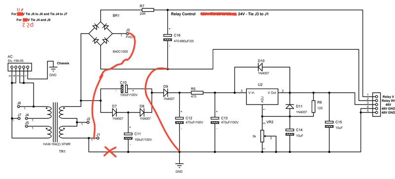
You are looking for Minimum Load Current, giving typical 3.5mA up to 10mA for the National LM317, other manufacturers show 5mA up to 12mA for this parameter. Just make shure, you pull enough for predictable results. This can be your always connected circuit behind (not true in your case as phantom can be switched off per mic for usual), around the regulator (your schematic) or something in between (and your R6). As you already noticed, depending on target voltage the required rating for R1 (your VR2) rises bejond standard specs when you want to pull the min.load thru R2 (your R5) only. Pull the rest thru a load resistor (your R6) instead.
Phantom power is 10mA per mic (ignoring 14mA max for dead short condition in your mic cable) times 2 for the other mic + always pulling 12mA for your VR2/R5+R6 plus some leakage current, so your quoted 10-25mA may be a little on the low side.
Your linked 'no output caps' quote seems to ignore connected circuits behind the psu (smoothing caps, IC-bypassing, ..).


[quote author="bcarso"]There is an odd discrepancy then between the quoted 783 prescription for good load transient response and what National shows for the behavior of the 117 (note that I went back and edited the link in my earlier post which didn't work with a comma appended).

National shows superior load response when the reference cap is used.

I guess someone should actually make some measurements.[/quote]
Texas Instruments TL783, page 8.
National LM117/LM317 , page 7.
I always imagined the 783 as a high voltage version of the 317. There may be more to it.
 
[quote author="Harpo"]Phantom power is 10mA per mic (ignoring 14mA max for dead short condition in your mic cable) times 2 for the other mic + always pulling 12mA for your VR2/R5+R6 plus some leakage current, so your quoted 10-25mA may be a little on the low side. "[/quote]


When u say "VR2/R5+R6", are these current values?
-I never thought of the reg circuit in current calculations.

my math is getting messed up.

Fo sake of argument using R1 and R2 as per 317 reg spec sheet...
R1=240
R2=9100
Yeielding a V of 48.65

I am getting 5.2 mA for R1 from 240/48.65
and 5.2mA for R2 from 9100/48.65

I can't seem to find the right calculations to get "12mA for your VR2/R5+R6"

I got 7mA for the 6k8 load though

Thanks for your patience
 
[quote author="guavatone"]When u say "VR2/R5+R6", are these current values?
-I never thought of the reg circuit in current calculations.

my math is getting messed up.

Fo sake of argument using R1 and R2 as per 317 reg spec sheet...
R1=240
R2=9100
Yeielding a V of 48.65

I am getting 5.2 mA for R1 from 240/48.65
and 5.2mA for R2 from 9100/48.65

I can't seem to find the right calculations to get "12mA for your VR2/R5+R6"

I got 7mA for the 6k8 load though

Thanks for your patience[/quote]
VR2/R5 + R6 isn't a valid formula but should show the location what is pulling current. Should have explaind it better. I'll try, please excuse my horrible english ...

You get 5.21 mA for R1 from 1.25V regulators reference voltage / 240R.
This is your current setting resistor since the reference voltage is constant.
You have this same current flowing thru any series resistor you put between reg.adj. and 0V. See these two resistors as a voltage dividing pot with the outer pins connected to reg.out and 0V and the wiper connected to reg.adj. For whatever reason you happen to have dialed in 240R between wiper and upper pot terminal. You know there is 1.25V across this part. You want a target voltage of 48.65V, so the voltage across the wiper and lower pot terminal must be (48.65V - 1.25V)=47.45V. As the current flowing thru any resistors in series is the same, from Ohm's law value of this resistor must be (47.45V / 0.00521A)=9100.8R.
Doublechecking this with your odd value pot total resistance (240R+9100.8R)*0.00521A you get your target voltage 48.65V.
(Datasheet formula 1.25V*(1+ 9100.8/240) gives the same result if you like it better.)

R6 at 6k8 is pulling (48.65V/6800) 7.15mA.
Adding both currents (5.21mA+7.15mA) you get 12.36mA.

If you don't want to calculate the current for each section separate and add up the results, you might see that R6 is in parallel to your voltage setting resistors at the regulator, so you will get the same result for current when dividing 48.65V by value of the resistors in parallel ( 1/(1/9340.8+1/6800)=3935.2R ), giving 12.36mA.

Hope this makes any sense.
 
Thanks for all your input Harpo.  Everyone's help gave me a better understanding for better PS design.
(sorry it took a while to respond)

The transformer is 20 VCT
Well, I tried this tripler with an added sub circuit for relay control.  The jumper on transformer secondary
was set for 24V relays and the 48V circuit was unconnected.

The problem is the XFMR is damn hot!!!!

R6=240
and VR2 is set for 9k3


48-relay-ps1.jpg
 
It seems this has become a grounding issue for me.  Now I will throw a monkey wrench into something fairly simple. 

The relay is controlling this funky auto switch circuit that switches between mic and line depending on whether the 1/4" Ring to Sleeve connection is shorted.  To the right of this schem(as well as layout plan) is a 2 valve preamp with a power supply for HT.  So I have 2 separate boards.  One for DC Heatwers, Phantom and Relay Voltage and the other for the Tube Preamp.  I was trying to avoid the ground path for the Audio going all the way through the Relay PCB to chassis.  The Preamp Board has one chassis connection now on a large chunk of copper that goes to the PWR xfmr CT and Filter caps.

Going with Harpo's plan would make a ground loop with the added schematic.  right?

On both schematics the GND symbol is my chassis star point.

di-relay1e.jpg
 
Back
Top