Newbie builds GroupDIY 51X rack

GroupDIY Audio Forum

Help Support GroupDIY Audio Forum:

This site may earn a commission from merchant affiliate links, including eBay, Amazon, and others.
chunger said:
Purchased 20-8 cable from Westmarine. 

p124716018.jpg

Ordered the same yesterday afternoon, and wow, it showed up today.  Looks good in person, fits the bill.  Flat rate shipping for me was $9.95, and it showed up overnight. 

Just for my own info on the next step (just using resistor color sequence on Neutrik pins for power):

1 = Chassis - brown
2 = Gnd - red
3 = +16V - orange
4 = -16V - yellow
5 = +48V - green
6 = +24V - blue
7 = -24V - violet

Since we get an extra wire and drain in this cable, I went with these additions.  The extra ground improves current carrying ability, and the drain gives some additional shielding. 

2 = Gnd - black
XLR shell = chassis - drain (connected at 51X rack end only)
 
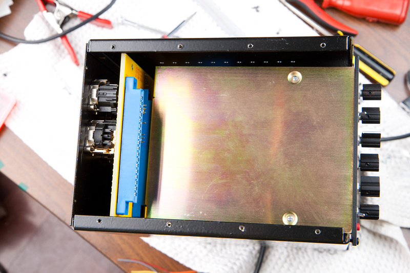
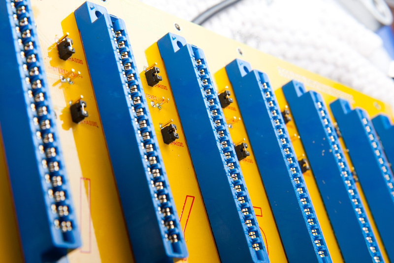
Important new discovery on my part and a critical error in the 51X build documented above.  I did not notice any problems until I built a Classic Audio Products LC53A EQ which has a full metal case as opposed to just an L-bracket like most kits I've assembled and run in the rack.

p259165415-4.jpg


Anyways, the LC53A is built to API external dimension specs and DOES NOT fit into the GDIY51X rack as built here.  Many LC53A builds I've seen run the module without its metal cover for this reason I suspect.  Knowing the backplane of the rack is 1/8" thick, I figured even with the best of tools, de-soldering the headers and installing them from the back side as they should have been installed in the first place could be a nightmare.

After some head-scratching, I devised the following simple solution that is minimally invasive and 100% functional.

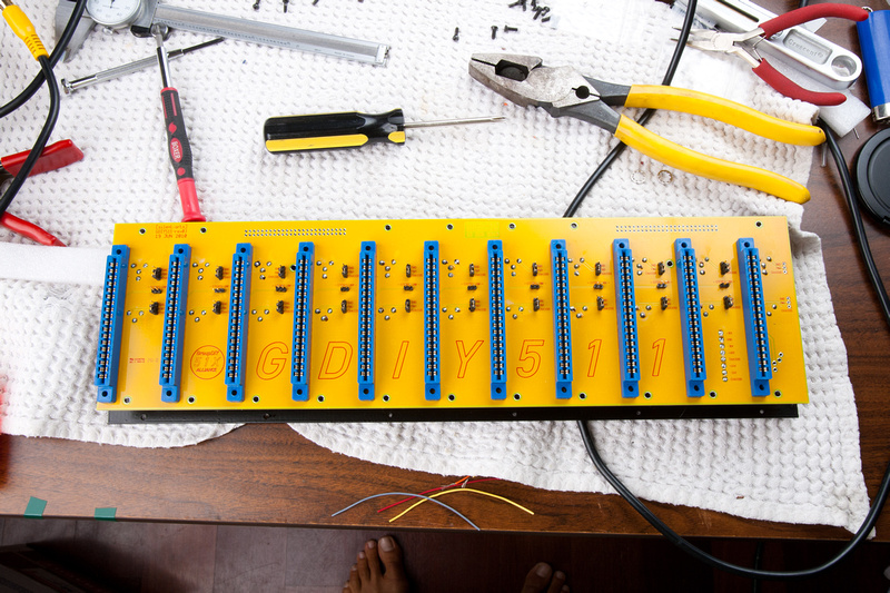
Remove the back panel from the 51X rack.

p143181251-4.jpg


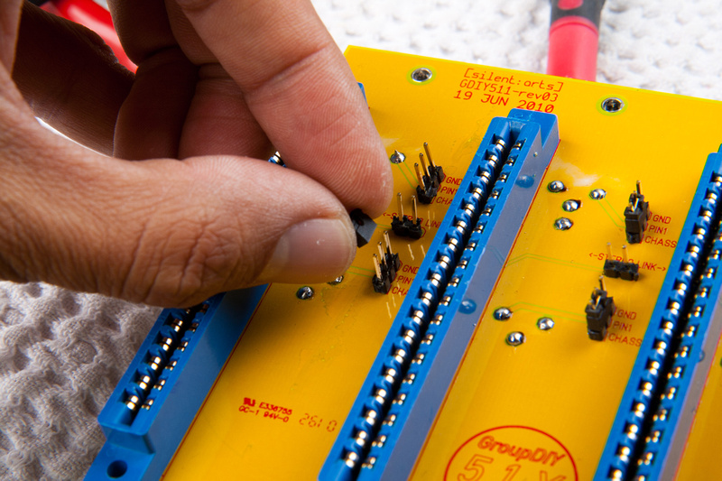
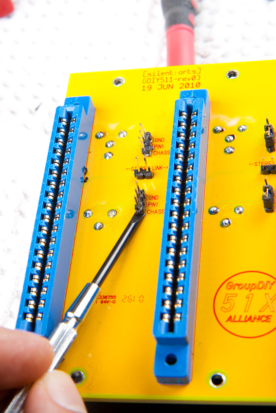
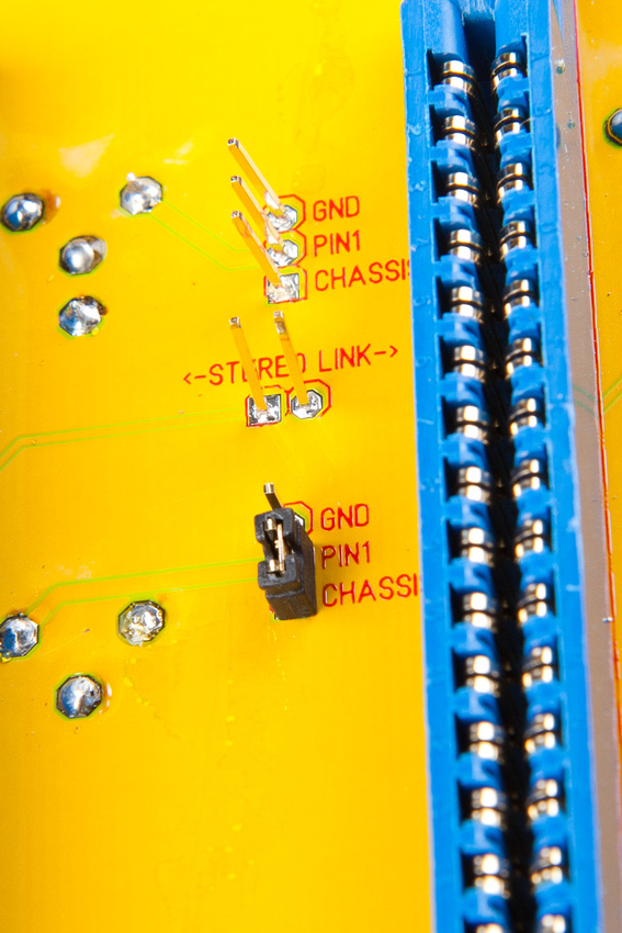
remove grounding jumpers.

p243820216-4.jpg


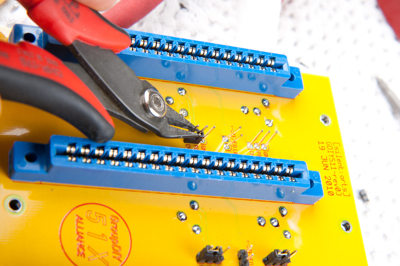
pry up the plastic portion of the headers with a screwdriver.

p329901056-5.jpg


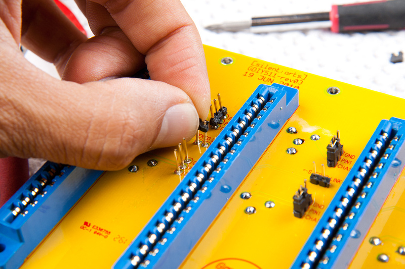
And pull the plastic base of the headers all the way off.

p445753570-4.jpg


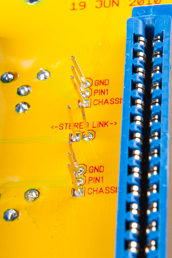
This will leave the metal portion free-standing on the PCB.

p301394942-5.jpg


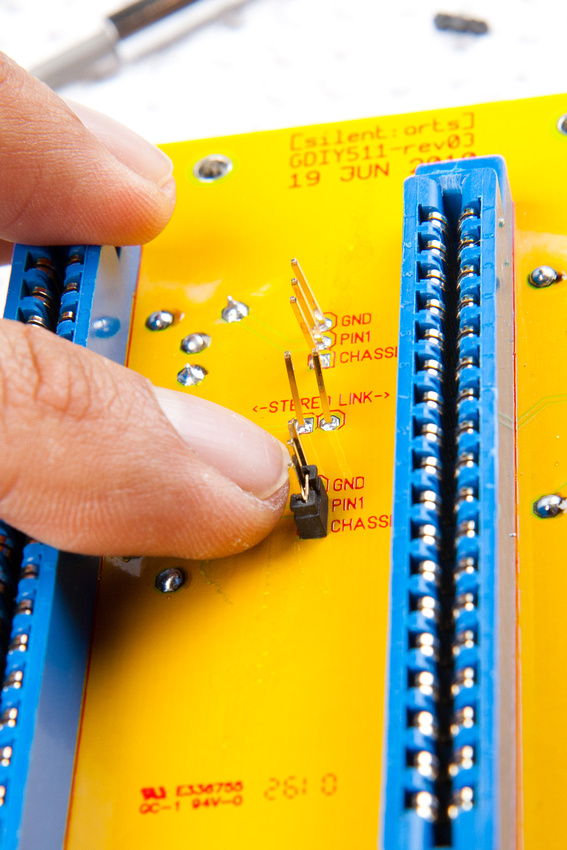
Next, re-install the jumper tight to the PCB.

p498598432-5.jpg


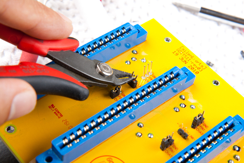
And cut the leads tight to the top of the jumper.

p521661285-4.jpg


This leaves the jumpers as close to the PCB as possible with the only drawback being slightly more difficulty inserting jumpers as the pointed guide edge is chopped off.

p514922938-5.jpg


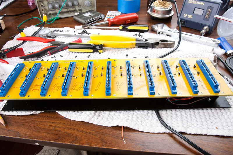
Continue with on with the rest of the jumpers until all are trimmed to length.
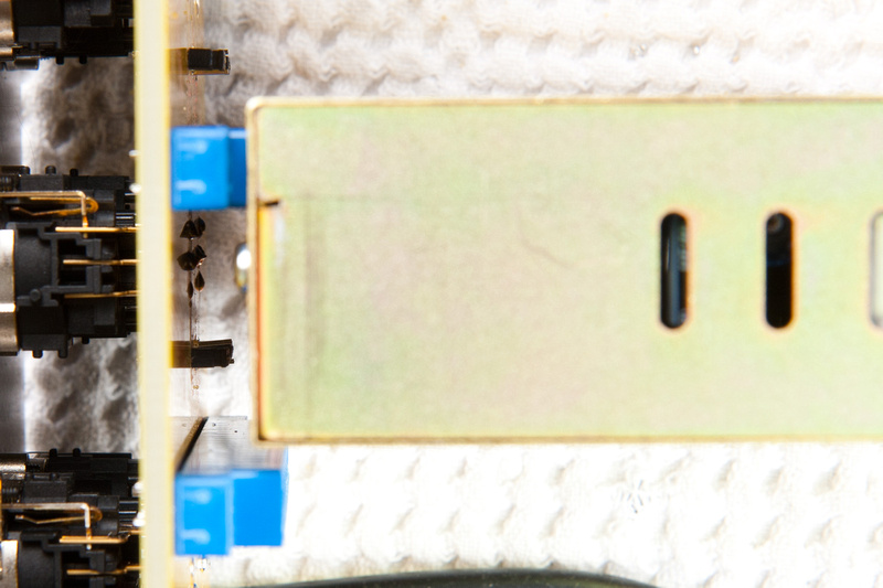
p451889844-4.jpg


p75526798-4.jpg


Nice and low now.

p475925571-4.jpg


No more clearance issues whatsoever.

p220650727-4.jpg


I apologize if this has caused folks headaches on their rack builds.  I hope the fix is simple enough.  Now, we can all go back to telling people how superior our DIY racks are and how they will never experience the wonders of +-24V 500 series awesomeness until they throw their hard-earned money to the 51X Alliance and repent of their lunchbox ways.  :eek:
 
Seems like I was lucky enough to solder in shorter headers,they didn´t exceed to card edge connectors nor did they reach the metal covers.
I had a look at them prior soldering and decided to put them in.
My Lovechildren fit like a glove.
So people look for short headers and jumpers when using full covered boxes.

Cheers,

Udo ;)
 
Yeah, no LC53A problems in mine, built with the header kits Jeff sells.  Thanks for the update. 
 
Hi Chunger,

How are you attaching the zip ties to the standoffs?  Looks like there is an extra white piece on the standoff for you to thread the zip tie through and around the wire.

Great build man.

 
Hi Guys,
I have been looking through the threads and I don't know if I missed it somewhere but what size length are the screws that we uses to build the rack enclosure and to mount the back panel with the PCB attached to the rack enclosure.  I know the are 2.5mm thread but what about the length.  I have a few that have seen better days and wanna replace them. 

Thanks
-Scott

or is 2.5mm the length what is the thread size / count?
 
Ok so based on my measurements the screws are 2.5m and 8mm long.  I can't find black ones at the usual online stores so where does the alliance order them from? 

Thanks
-Scott

Thanks to Jeff I found them here.

http://www.mcmaster.com/#95836A255

 
Hello people! I'm just about done with my 51x rack, only have the power connector left.
I do have some fancy looking cables at hand, though they are quite thin and I'm not sure if they will work. I attached an image of the cable with the connector. Help on the subject much appreciated :)

/Simon
 

Attachments

  • photo.JPG
    photo.JPG
    414.6 KB · Views: 49
This is really rather brilliant - I have re-wired pro studios in the past (way back in the day)- but never been near pcb soldering - this thread really inspires me - and I really resent the prices of most of the 500 series racks. This 51x alliance is brilliant - 24volts - it changes everything - or at least the extra pins too do! I feel like a fraud joining this forum - but the whole deal seems so supportive which is splendid after spending more than 90 seconds on gearslutz can be very spiritually toxic.

So Thanx Y'all, I'm happy to have found this forum.

Be Well - WD :-*
 
What is the easiest way to add a DB25 pin out to this, so I can hook up at least 8 channels to a patch bay?

- It looks like there is a 50 pin connection to ribbon.
 
Back
Top