Western Electric 111c wiring/parts help for a passive color box

GroupDIY Audio Forum

Help Support GroupDIY Audio Forum:

This site may earn a commission from merchant affiliate links, including eBay, Amazon, and others.
Thanks for this post. I have some line level xformers out of a beat to crap Sunn mixer I plan to gut and experiment on the outs of my yamaha pm 3500.
This has been VERY helpful especially the link to the 600 ohm T pad....
The thread died. I think I asked too many questions. lol
 
People make them from stepped switches usually. If you don't want to make them, check out goldpoint or daven

You have the 600:600 wiring figured out, which is the primary and secondary both series. To switch to 600:150, switch the secondary to parallel.

You have balanced signals so there is a (+) and (-) coming in on each XLR. You don't have to switch the ground, but you do have to switch the (+) and (-), so each needs a 2P. For full bypass, then you need 4PDT for both left and right.


Just A/Bing. You need to decide if you want it or not.


That doesn't make any sense. Read about balanced signals.

Thanks very much for the reply.

Sorry, I got confused. disregard that statement about the stereo jacks being unbalanced. i meant bridge negative to ground, but I understand the circuit now. For some reason I misunderstood something I read about using unbalanced cables with it. I completely get it now.

As far as the switches go I basically do the same thing as the left side in that diagram I sent, but for both positive and negative correct?


I ended up ordered the hairball audio Tpad... I guess in the future I can always upgrade if need be. I'll just have to calibrate each time I want to use for mixing/mastering. Any other suggestions for brands? I'm aware Elma's are high quality and usually used in mastering.


I found a diagram for the 150 switch wiring. This one also has a phase switch, but I'm not sure why I'd need to add that. I've attached the diagram, and what I think is the way to wire up the switch for the 150 ohm switcher. I could be wrong though. Any guidance greatly appreciated. I'm just unsure if attaching the terminals from 7 and 4 will work or do I need to attach them at the jack. or is does that not matter either way?


111c(1).jpgScreen Shot 2023-01-24 at 1.27.05 PM.png
 
As far as the switches go I basically do the same thing as the left side in that diagram I sent, but for both positive and negative correct?
Draw out a full schematic for it, with the XLRs, both 111c, bypass switchs, Tpads, and impedance switch. The bypass switch for each side switches the + and - for input and output.

I found a diagram for the 150 switch wiring. This one also has a phase switch, but I'm not sure why I'd need to add that. I've attached the diagram, and what I think is the way to wire up the switch for the 150 ohm switcher. I could be wrong though. Any guidance greatly appreciated. I'm just unsure if attaching the terminals from 7 and 4 will work or do I need to attach them at the jack. or is does that not matter either way?
Yes, that is correct for impedance switching.

I ended up ordered the hairball audio Tpad... I guess in the future I can always upgrade if need be. I'll just have to calibrate each time I want to use for mixing/mastering. Any other suggestions for brands? I'm aware Elma's are high quality and usually used in mastering.
Assume you meant you ordered a pair? You'll need one for L and one for R.
 
Draw out a full schematic for it, with the XLRs, both 111c, bypass switchs, Tpads, and impedance switch. The bypass switch for each side switches the + and - for input and output.


Yes, that is correct for impedance switching.


Assume you meant you ordered a pair? You'll need one for L and one for R.

Thanks, I'll draw up a schematic. Yeah, I ordered two Bourns Tpads. I'm just now realizing i should have added that PCB for easier install. I suppose I can still wire it up even though it's PCB mount. Or would you recommend ordering them?

are the pins on the top left and not right of this diagram below not used? Also what about the 4 corners? Looks like I just need to ground the middle three pins together, connect the negative goes to the top middle, and the bottom left and right are the positives. That should work wired up right? EDIT: I ended up ordering them anyway. I still might try to wire it up without them if they don't arrive in time.

1674622651443.png
 
Last edited:
People use the 111c when they want to kick the bass in the ass. Yes they have a crazy big core. It is a strip wound chunk of steel that would turn your big toe into blackberry jelly if you were test Newtonian physics.

The wire is cloth served, kind of like a stale mummy, so reliability is questionable.

Throw in the mercury impregnated shields and you have a real interesting coil on your hands.
 
Ok... I think this is the everything correctly drawn out. Let me know what you think. I'll be putting it together later today or tomorrow.


Draw out a full schematic for it, with the XLRs, both 111c, bypass switchs, Tpads, and impedance switch. The bypass switch for each side switches the + and - for input and output.


Yes, that is correct for impedance switching.


Assume you meant you ordered a pair? You'll need one for L and one for R.
 

Attachments

  • yes 111c.jpg
    yes 111c.jpg
    386.8 KB · Views: 0
Close - connect 1 6
You are switching the input side from 600 to 150 instead of the output. This means you will be stepping up 6dB instead of stepping down 6dB
 
Close - connect 1 6
You are switching the input side from 600 to 150 instead of the output. This means you will be stepping up 6dB instead of stepping down6dB

Thanks for the heads up on 1 to 6. I forgot about that jumper.

Do you think it's better to step down, or will that impedance change fuck up how my mix bus gear interacts with it? I guess to swap it I just move 4 to 2, and 7 to 5 in order to do the reverse right?
 
Last edited:
Yes, just like the diagram you posted above. Why don't you listen before deciding? I don't know what is "better", you need to decide what you want.
 
Thanks for the reply. Good point... I will likely be using it as the last step in my chain. So whatever would prevent least problems interacting with the gear will most likely be best solution. I'll test anyway just to see.

I'll let you know whenever I have it wired, and results.

Here is the updated diagram with the 150 on input now.
 

Attachments

  • wiring 150 ohm in .jpg
    wiring 150 ohm in .jpg
    389.9 KB · Views: 1
Yes, just like the diagram you posted above. Why don't you listen before deciding? I don't know what is "better", you need to decide what you want.

Whoops. I forgot to account for the T-pad in my last diagram. Pretty sure this is the correct spot. Let me know what you think. Thanks.
 

Attachments

  • wiring 150 ohm in with volume.jpg
    wiring 150 ohm in with volume.jpg
    438.3 KB · Views: 0
Yes, just like the diagram you posted above. Why don't you listen before deciding? I don't know what is "better", you need to decide what you want.

Alright I got it wired up.

It sounds great, but two things. The right channel is inducing a .6db drop even when in bypass. Any idea what could be causing this? Could it be the tip isn't making a strong enough contact in the trs?

2nd - Something must not be wired wrong with the 150 ohm switcher. 600 ohms is coming through just fine. Can you take a look at that switcher diagram on the 4pdt.
 
The right channel is inducing a .6db drop even when in bypass.

How exactly are you measuring? That is small enough difference that you have to double check everything along the path (including a test without your new box at all, i.e. connect output cable directly to input cable and make sure it isn't e.g. high resistance in one of the cables or connectors).
 
How exactly are you measuring? That is small enough difference that you have to double check everything along the path (including a test without your new box at all, i.e. connect output cable directly to input cable and make sure it isn't e.g. high resistance in one of the cables or connectors).
Thanks. I'll check the cables. I was just using a 1k test tone in L and R channels.
 
I was just using a 1k test tone in L and R channels.

Then step 1 would be to verify if the output of the L and R channels are actually matched closer than that. You could for instance swap the connections to L and R going into the box and see if the level difference follows the box channel, or the output channel.
 
Verified that it wasn't the cables. Then it occurred to me to check the interface. doh! Problem solved. For some reason channel 3 only on my interface had a -.6 db adjustment. No clue why it was there but that fixed it.

As for the ohm switcher. I moved wires 8 to 4 and 3 to 7. I believe this changed the input side to 150 creating the step up function. It added a few dB of gain. I will probably leave it for this function rather than step down. Won't likely use it over 600ohm because I notice a smearing in the low in that I'm not hugely fond of.

But anyway, we have success! Thanks to everyone for listening and answering all my questions. I hope somebody in the future finds this thread helpful.
 
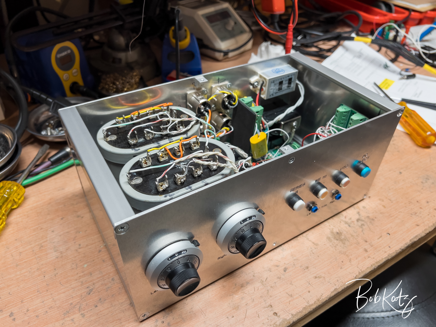
Bob Katz shares his transformer color box with REP-111 measurements.

https://proaudiodesignforum.com/forum/php/viewtopic.php?t=1333
Katz_IMG_006005.jpg
 

Latest posts

Back
Top