What Should I Do With a 1966 Denon Tube Reel 2 Reel?

GroupDIY Audio Forum

Help Support GroupDIY Audio Forum:

This site may earn a commission from merchant affiliate links, including eBay, Amazon, and others.
Thanks for the input. Although I do have an oscillator, RMS meter, and scope, and can probably run enough tests to get it 'tuned,' I get the impression that this ol' Japanese Denon probably isn't worth it.

It DOES however have a beautiful power supply & meters sitting in a decently solid rack-mountable box with tube sockets and probably many of the resistors and caps that I need already floating around in there...

I DO however need a nice stereo (or 4 channel!) tube DI....

It's looking like it's going to be similar to NYDave's Two-Bottle-One-Bottle topology..
 
Here's the quick and dirty sketch of the Denon Mic Preamp :? Yes, the K caps are 50uF electros and ALL of the coupling caps are .05uF. Bass rolloff for mic preamplification I guess. No input cap either. It looks like the mic/line switch switches to the second AX7. Each channel is 1/2 of the AX7.

DenonPre.jpg


Any OP transformer recommendations? As it stands I'm thinking I'd like to use a 1:4 or 1:10 on the input... Maybe have to re-bias the tube to gain a little bit-o-headroom...

I'm thinking about (poker terms) seeing those 50uF electros and raising them another 150-300uF. I'll raise the coupling caps a tad too I think.

All of the mic controls are on the left with enough switches for a -20dB pad, Phantom, Phase, & a negative feedback gain control.

On the right hand side of the VU meters there's enough room and sockets left to do a simple vari-mu compressor... Maybe a gate I don't know. Any recommendations on that one? PRR's comp looks kinda cool, I'm thinking about that topology.

There are already (2) 12AU7 tubes socketed there sort of next to the PSU rectifier tube (playback?) There is a third 12AX7 after the preamp which I believe are used to drive the recording heads. I could use these tubes as an additional stage at lower gains to assist the (non) linearity of the compressor/gate add-on. Or, should I use these to cascode the preamp stage?

Oh yeah, I do have a bunch of opto stuff if anyone can point me to a few diagrams of some SIMPLE tubey optos. There's a multi-pos. switch at the right hand side where I'd eventually like to change either the attack/release settings or the knee curve... Eventually...
 
At least one if not two tubes drive the meters, I bet.

Can you roll 2 G9's out of it? Enough B+ and current? Heater leads 12.6 or 6.3v? Rectified heater voltage or straight ac? Measure voltages and component values to see if they're on or drifting? B+ clean? etc etc

What's the playback circuit look like, from the head to the unbalanced output? That's usually the best sounding circuit in a tape recorder. That mic pre is just a crappy go between to dangle a plastic dynamic mic off of.

The heads should be hi-z, so you can expect similar performance from an input xt where the playhead was. If they're low z then there should be an xt already in there, between lo-z heads and the first grid. Put something like .22uf or .47uf in front of the first stage of the playback line amp, xt if you want. If you're feeling whacky hook your discman up with a 400v cap, .22, .33,.47, where the playhead was and plug the output into your stereo, see what it sounds like, how much gain it has, yadda yadda.

There should be a bias transformer in there for erase current.

'Cause think about it, these were playback machines, folks bought tapes as well as lp's. There wasn't any serious thought put into the recording capability, as long as little Billy could drive his Dad nuts with the slap echo thing, and maybe record a radio broadcast once in a while, make a 3 and 3/4 ips Xmas party tape, etc.

I'll mention the 351 only briefly because I don't want to go there, but the mic pre is basically what a fellow Ampexian calls a Suck Button; the balanced line in was a fat pad in front of the mic pre. I have a Captiol Records 350 with numerous Capitol mods, and guess what? They gored the mic pre. The machine was set up to take unbalanced bridge in ONLY. So it's said of the Columbia 350s and 351s.

But if you look at the scheemo of the TubeTech MP 1A mic pre it's the *playback* line amp from the Ampex 351, complete with the fancy output xt, feedback winding to cathode of invertor, blah blah blah.

That would be a cool copy; 12AX7 gain, 12AX7 invertor, a single 12AU7 in pushpull and the 351 output from Sowter.
 
The PSU is 6x tube rectified at @320VDC. There is a line of series resistors which are tapped at everwhere from @250V all the way down to 110V for the first AX7 for the playback heads.

The heaters are push-pull 3.325VAC, or 6.65VAC... :? I'll have to convert those somehow. For now, they'll be AC...

Here is the schemo from the PB heads to the EQ. Yikes! look at the K cap for the second AX7... Quite an EQ curve there. Is that normal?

DenonPre2.jpg


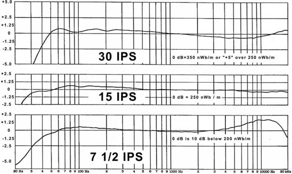
This is an EQ curve I googled. It looks nothing like the curve that this amp would make. Did I accidentally follow a meter driver? :sad:

tapelo3g.JPG


I didn't follow this past the EQ stage, but I'm guessing a P-P AU tube follows as previously suggested. This EQ is switchable for different tape speeds. I'd like to know what I have to work with in there, and if it has to be gutted out.

Feel free to send me ideas! :thumb:
 
[quote author="northsiderap"]This is an EQ curve I googled. It looks nothing like the curve that this amp would make. [/quote]

Because it's not a EQ curve, it's the resulting frequency response you would get on a Studer B67....
Tape EQ curves look way different. Sorry, I don't have any pictures at hand, but if you really need something I could scan them.

Olaf
 
[quote author="NewYorkDave"]Brad, did you document Capitol's mods?[/quote]

Hi Dave, have yet to trace the rats nest they made of these things, but that's a good meditation to attempt. They added ground lift, fiddled termination, yanked the meters and set them in a fake-o 300 meter panel--no controls--moved calibration pots to the meter holes, then covered them square engraved black plastic covers w/ machine designation. Mines "Capitol 32"

George Showerer says he has docs on the Columbia mods; really, they just eliminate any possibility of going through the xt and first half of the 12AX7. Driving the unbalanced line was probably the trick to that, had to be a typical little driver box.

We just had our semi annual **** storm over 351's as pre's over on the Ampex Hall of Fame list...
 
[quote author="northsiderap"]The PSU is 6x tube rectified at @320VDC. There is a line of series resistors which are tapped at everwhere from @250V all the way down to 110V for the first AX7 for the playback heads.

The heaters are push-pull 3.325VAC, or 6.65VAC... :? I'll have to convert those somehow. For now, they'll be AC...

Here is the schemo from the PB heads to the EQ. Yikes! look at the K cap for the second AX7... Quite an EQ curve there. Is that normal?[/quote]

Hmm. I don't see the feedback. Eq is usually nested in feedback. What resistors do the eq switch change/drop ot. You'd junk the eq anyway.


I didn't follow this past the EQ stage, but I'm guessing a P-P AU tube follows as previously suggested. This EQ is switchable for different tape speeds. I'd like to know what I have to work with in there, and if it has to be gutted out.

Feel free to send me ideas! :thumb:

Hmm p-p would drive an xt, you're either right off the plate or a cathode follower. Trace the rca output back to a tube.

I'll draw a simple pre ciruit for 2 12ax7 and one 12AU7 that begins around 250v but I can't host. Somebody hit me with an e-mail addy if they'd like to see it &/or post it here.

Yeah, your first scat could be the meter driver. Is this thing point to point or boards?
 
This thing is P2P..

Yeah, ther is no OP XFMR :oops: so: no P-P OP. My bad. I've only designed class A stages for preamps, and have never wandered into class B territory before.

email northsiderap @ yahoo.com if you want me to host.

There is free webhosting with hotlinking at geocities.com too.

I use mainly hot condensers and decent dynamics so I'm probably not going to strive for anything above @50dB for gain.
 
[quote author="northsiderap"]This thing is P2P..

I use mainly hot condensers and decent dynamics so I'm probably not going to strive for anything above @50dB for gain.[/quote]

Okay, that's easy for dynamics: there should be a resistor hanging off the grid to ground on the mic in.

If you use the playback circuit as the pre set it up like Jakobs G9 input, switched 1/4" jack that jumps in after an input tranformer you would put in. If you're replicating the deck's playback as mic in, use that same resistor value and hang it off the grid to ground following the mic. Personally I'd hang it off the jack ground and insert the jack AFTER the xt and input cap you install; just jump past the xt & cap for dynamic.


Now: the 1st playback tube circuit and the 1st mic in circuit *should* be very very similar, if not exactly the same, except the playback will have eq junk dangling off the cathode or something, an extra cap maybe, usually adjustable. If, once you've traced this, it's the case that both first stages are nearly identical, use the first mic stage and the second playback stage as your circuit (or just strip the eq off the playback tube.)

Get some of those OEPs from Newark to try stuff out, highest turns for in, and out you'll have to figure based on you output z. Unbalanced consumer outs on tube stuff was usually 10-15K, anybody feel free to correct me if I'm sounding offline.

Check out Jensen's ap pdf's to balance consumer unbalanced out. He shows his direct box xt in one circuit, but if you're using this in your main recording rack be aware of levels mismatch, -10, +4, etc. He has a scheemo and xt that deals with matching levels specifically, I think it's a JE-10KB or a 6110 or one of those iirc.

Point to point should be pretty easy to follow around, ignore the line in jack, it's usually just line through, going to second gain stage and out. Line in to record would do the same thing, skip the 12AX7 and go right to the second gain, 1/2 a tube. The second half of the same tube would drive the record heads.

It's hard to say where they might have put the meters but they usually sits between the first tube and the second tube, driven by a 12AX7 in most cases. One tube per meter.

Dual meters? Switchable single meter?

If you actually trace through those multi wafer switches you'll get the Switch Decoder merit badge, man; that **** gives me brain cramps...

I'll draw this li'l circuit (with a pencil) and mail it to you in a sec.

If this thing actually spins at 30ips I'm Fidel Castro...
 
Here is a set of updates... I kinda rushed through the first trace. I finally had some free time to get more aquainted with the amp.

Mic Pre:

DenonMicPre.jpg


Line Amp:

DenonPBAmp1.jpg


The play head amp is the simple 2x 12AX7 before the EQ. Not done tracing that one through the EQ yet.
 
The second triode in the first schematic, and the first triode in the second schematic have grids that are floating at DC. That can't be correct. Did you overlook some grid resistors there?

The second schematic shows two cathode followers, one of which (the upper) is apparently doing nothing.
 
I did re-check everything and couldn't find a the grid R... Perhaps they were using grid leakage and skimping on the high-value R?

I will check again now that you asked...

Does anyone know if it would be prudent to remove some of the K bypass caps for a little bit less gain?

[EDIT] I did find a 100k grid [EDIT] RESISTOR on the line amp, but not on the mic amp 12AX7 with the negative feedback...
 
[quote author="NewYorkDave"]

The second schematic shows two cathode followers, one of which (the upper) is apparently doing nothing.[/quote]

If there's no signal output then it's the meter driver.

What's the "eq"? Tone controls for playback? I don't know if you're referring to passives in the circuit for a playback eq curve (NAB, CCIR, etc.) or...
 
[quote author="AnalogPackrat"]I think NYDave means the top CF has no input signal as drawn![/quote]

Right, my bad.

Hasty translation: If the cathode of the first 12AU7 triode hit the grid of the 2nd triode, rather than going to a meter as drawn, and the 2nd triode cathode follower drove a single meter, this would make sense to me. There should be a pot between the cathode and the meter though, for calibration.

Actually, no, that's not right either, cuz the plates are coupled as drawn...

I think instead of pieces of scheemo draw maybe the whole record circuit and the whole playback circuit, each from beginning to end.

Personally I wouldn't chop any caps out right away.
 
LINE OUTPUT AMP:
The line amp is actually the output line amp. The meters and the OP RCA jacks are basically tapped in the same place following the OP cap of the CF 12AU7.

The top CF is shown because I needed to couple the plates for proper simulation, so YES there is a second AX7 and signal source for the other output. The meter pot is actually inside of the meter, so it wasn't properly measured.

I put a 1ohm resistor in where the record level pot is on the mic amp. The record level pot is actually preceded by a fixed 200k resistor.

MIC PRE:
The line in switch is after the first 12AX7 of the mic pre. Immediately following the line in jack is a record volume pot that shunts signal to ground before the second 12AX7 stage.

POST THE ENTIRE SCHEMATIC:
If someone wants to buy me a license for Circuitmaker I'll start posting whole schematics - - until then I'm stuck with pieces of everything...
 
[quote author="northsiderap"]

POST THE ENTIRE SCHEMATIC:

If someone wants to buy me a license for Circuitmaker I'll start posting whole schematics - - until then I'm stuck with pieces of everything...[/quote]

Oh c'mon.

Pencil. Scanner.

Include the pots in your scats rather than replacing them with stuff, include everything that's actually there; it's too hard to figure out what's what, for me anyway.

Does this thing have a model number?
 
[quote author="bradzatitagain"]
Oh c'mon.

Pencil. Scanner

....Does this thing have a model number?[/quote]

Pencil: I have one!
Scanner: Sorry.

Perhaps I'll try to paste them together in Photoshop. I'm having a bit of a hard time working around some of the switches & relays tho... There is a large bank of relays, and most of the switches are DPDT hidden behind a shield which is thoroughlly attached to the chassis.

I've searched for a model # and I can't find one.
 

Latest posts

Back
Top