Analog_Fan
Well-known member

Simulation of the circuit
according to the simulator it works perfect, but what would be the benefit?
input is 10V.p.p and out is 24V p.p.,
it's the output section of this:
Hexmix - Befaco
schematic


...Don't neglect the possibility I have missed something and I'm utterly wrong.
The original schemo is correct in this respect (reversed transistor). However it is a quite complex circuit for replacing a single resistor."That circuit isn't working as it should. You need to swap the E and C terminals of the upper transistor, and change the resistor ratios in the NFB."
")
How did you calculate or envision that?There is no "philosophy" here.
It is a basic inverting stage with Vbe multipliers in the feedback, which is supposed to contain the signal whenever it tries to exceed a certain level.
It's often misappropriatedly called a "limiter", but in fact the proper name is a clipper.
It's a somewhat "soft" clipper because the level containment happens over a relatively high range of level.
This circuit is the basis of many overdrive/distortion pedals. It's also used in applications where excessive peak levels must be avoided, such as AM transmission (CB, walkie-talkie...).
Distortion increases as level approaches the clipping level, so it's not a clean limiter.
BUT: with the actual values, clipping appears at about +100/-120V at the output, which can never be attained wit +/-15V rails.
I'm giving it a shot as well (since it will take some time to get parts and PCB), spend the last fews hours creating, revising footprints for SOT666, SOT457, SOT363 for BCM847, BCM857.So, either there is a significant mistake in the printed values, or whoever designed the circuit took it from a cookbook and didn't know how to tune it.
A better operation could be achieved using complementary transistors, for equal positive and negative clipping.
Thanks, that escaped me and for the help.Note that you have transcripted the schemo wrong. The upper transistor has its collector to the right.
Don't neglect the possibility I have missed something and I'm utterly wrong.
the B.O.M. says 15K, as does the schematic, it was caused by because i can't zoom in further (max 97%) and it takes time to render that pdf.So, either there is a significant mistake in the printed values, or whoever designed the circuit took it from a cookbook and didn't know how to tune it.
Schottky diodes or normal 1n4148?I had not seen that the 220k is in the middle of two 15k resistors, not 1.5k. With these values, clipping appears at about -12/+10V.
These are sometimes called diode break amplifiers, the diodes in the feedback network conduct at different voltages changing the transfer function.View attachment 93422
Simulation of the circuit
according to the simulator it works perfect, but what would be the benefit?
input is 10V.p.p and out is 24V p.p.,
it's the output section of this:
Hexmix - Befaco
schematic
Even after correcting that mistake, simulation shows that clipping is not symmetrical. That is not a big issue, since the sound quality is already degraded when it happens, but it just shows the designer did not exercise the best of his talent...Yes, just a drawing error, the emitter and collector are reversed on the top transistor.
this is how it sounds.Even after correcting that mistake, simulation shows that clipping is not symmetrical. That is not a big issue, since the sound quality is already degraded when it happens, but it just shows the designer did not exercise the best of his talent...
It is good design practice to make clippers symmetrical. Clipping in one polarity before the other introduces a DC component into the signal... Some circuits can ignore varrying DC content, others don't. YMMVthis is how it sounds.
(since Befaco employed this circuit in another design before the mixer, that's where i discovered it some 2 years back, i assume they also used it here, on this module the didn't publish the schematic.)
as long as i have chosen the right resistor value and leaves 10V.p.p. clear and untouched accept when exceeding that "design requirement", it should be good.
it's still a weird but cool looking circuit.These are sometimes called diode break amplifiers, the diodes in the feedback network conduct at different voltages changing the transfer function.
For small voltages the feedback resistors dominate. When the output voltage is large enough to turn on the bottom NPN the output voltage is clamped (clipped). The steering diode doesn't conduct in this path for negative voltage swings. During negative voltage swings the top NPN reverse connected base-emitter junction zeners at roughly 6.8V.
The "philosophy" is unclear... asymmetrical clippers will generate different sounding distortion from symmetrical clipping. There is a possibility that the top NPN is drawn incorrectly. Reversing it would make a symmetrical level clipper.
JR

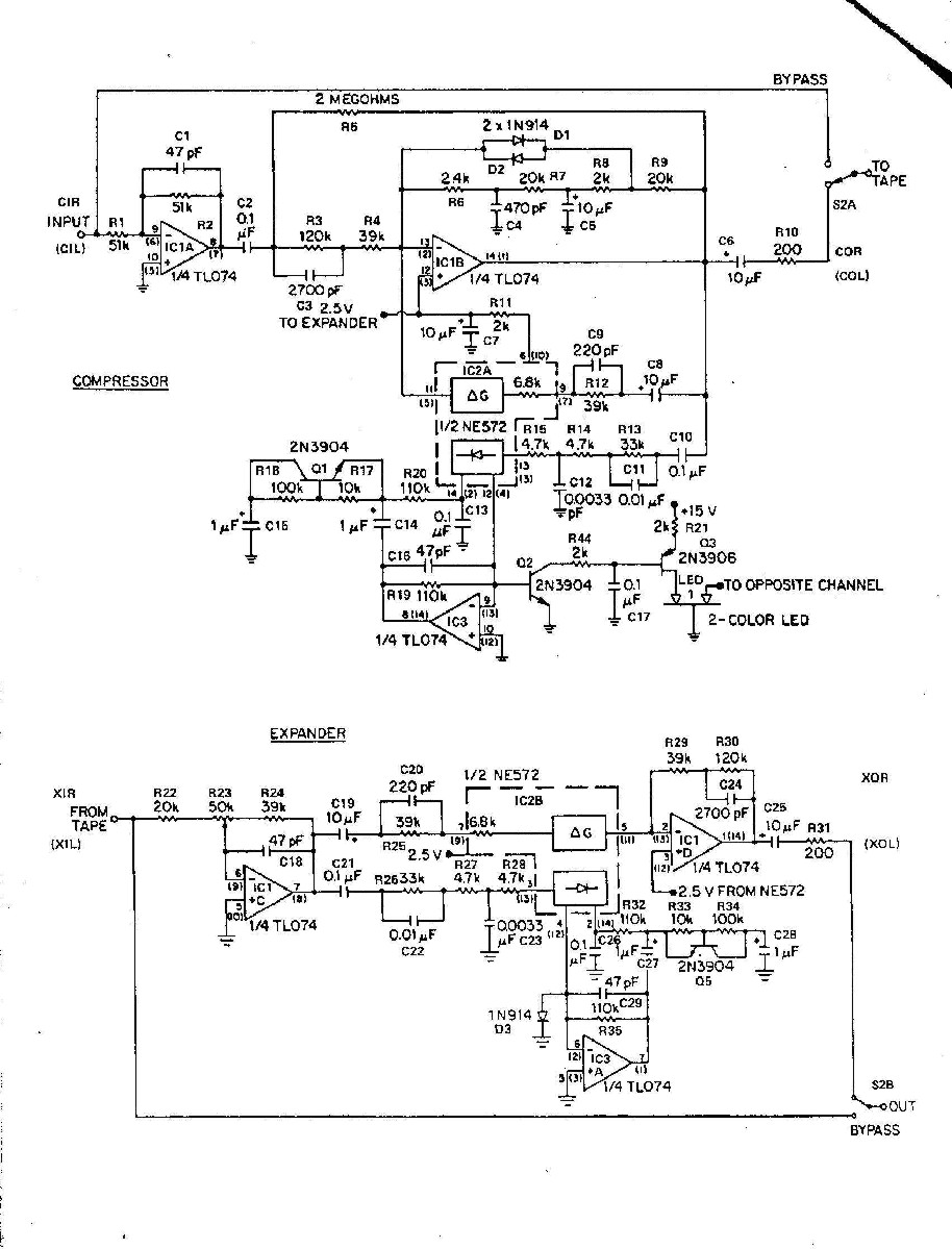
the circuit around Q1 (2N3904) is interesting.That is part of the challenge from working with old hand drawn schematics (guess the actual circuit design).
For another example of a diode break clamp/clipper
There is a lot more going on but the two anti-parallel diodes near the top of the schematic create a soft clipper, to protect the ne572 gain element that would spike if its max current was exceeded.
JR
don't own a spectrum analyzer yet, to expensive.B is less simple (and less linear) where output follows input until diodes run out of current and pull up/down resistors dominate.
C is a Analog Devices precision rail to rail opamp.C looks like one of those hand drawn schematics that doesn't make sense.
don't hurt you head... that is a very complicated circuit using features inside the NE572 in ways other than the IC maker intended. To understand that circuit you need to understand the innards of the NE572 (a cheap compander IC from last century).the circuit around Q1 (2N3904) is interesting.
i would never come up with C9 and R12.
: )
Its a compander for tape noise reduction... compress the input then expand the output (similar to dbx NR. The goal is end up with a transparent recording reducing the tape noise floor.seems like a compressor, but the normal feedback is 44.4 k and the seemingly optional path is 45,8K (if that's a vactrol).
not sure what it is.
If you have a computer and a soundcard, it takes only loading one of the free softwares and you're good to go. REW, ARTA, Audacity...don't own a spectrum analyzer yet, to expensive.


![Soldering Iron Kit, 120W LED Digital Advanced Solder Iron Soldering Gun kit, 110V Welding Tools, Smart Temperature Control [356℉-932℉], Extra 5pcs Tips, Auto Sleep, Temp Calibration, Orange](https://m.media-amazon.com/images/I/51sFKu9SdeL._SL500_.jpg)


