what would be the philosophy behind the opamp configuration?

GroupDIY Audio Forum

Help Support GroupDIY Audio Forum:

This site may earn a commission from merchant affiliate links, including eBay, Amazon, and others.
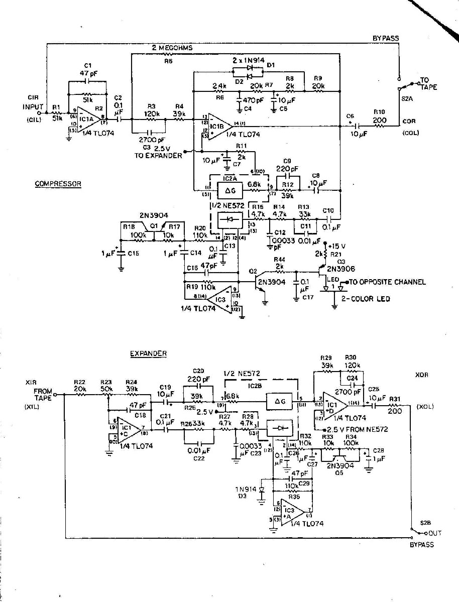
Its a compander for tape noise reduction... compress the input then expand the output (similar to dbx NR. The goal is end up with a transparent recording reducing the tape noise floor.

JR

off topic: I got a Akai MPC X, I'm hoping a Urei 545 and a LA-A2 or similar clones (i build later on) will return some analog feeling, because it sounds too perfect.
Any ideas how to make a perfect sounding device sound device sound somewhat less perfect?
 
Even after correcting that mistake, simulation shows that clipping is not symmetrical. That is not a big issue, since the sound quality is already degraded when it happens, but it just shows the designer did not exercise the best of his talent... :)

Not sure that is a fair conclusion without knowing the designers intentions. Non-symmetrical clipping is often desirable for some applications.
 
That is part of the challenge from working with old hand drawn schematics (guess the actual circuit design).

For another example of a diode break clamp/clipper
p-522.jpg

There is a lot more going on but the two anti-parallel diodes near the top of the schematic create a soft clipper, to protect the ne572 gain element that would spike if its max current was exceeded.

JR
I'd like to add a "mini-rant" here. The compressor/expander schematic posted earlier in this thread is a good example of how NOT to draw schematic diagrams!. It is inherently prone to misinterpretation after a few generations of copying, printing, or scanning. Look at the vanishingly small size of decimal points - and the junction style of the wires! A couple of simple rules can essentially remove those possible errors:
1. No decimal points in component values. Use the multiplier prefix to denote the decimal location, i.e., 4.7 k becomes 4k7 and 3.3 ohms become 3R3. For capacitors, use all multipliers, so that .01 uF becomes 10n and 4.7 pF becomes 4p7, etc.
2. Forbid both 4-way junctions (using a single dot) and the wire crossing with the "jumper hump". That way, you know that when wires cross, there isn't a junction no matter how big the blob that forms after generation of copies. Likewise, the jumper hump can become indistinguishable from a 4-way junction with a single dot. Some older schematic capture programs enforce these two rules in their automatic checker.
I'm well aware that most pre-1960s schematics even used uuF to avoid the other dreaded prefixes like pF (pico). But today, the nF (nano) seems to have the same dread attached. But everyone embraces G (giga) ... but I've actually seen old literature using kMC for kilo megacycles! Old habits do die hard, but if you're generating a new schematic, do try to eliminate ambiguity!
 
Then again , look at the Rolling Stones mobile and its Helios , you can hear the A symetrical clipping all over the records it produced , still great records though
 
Then again , look at the Rolling Stones mobile and its Helios , you can hear the A symetrical clipping all over the records it produced , still great records though
My schematic rant is about schematics that are drawn wrong.. These days most schematics serve as front end data for CAD. If the computers can't read it the fab doesn't happen.
=====

Do you see the woofer cones slowly moving in and out from the DC content generated by "asymmetrical" clipping?

I used to design tape NR and unintended LF content like warped or out of round records (hole not centered) could cause problems, especially if the compander had wider LF response, than tape... (almost any path has more LF than cassette tape :rolleyes:). Before I figured this out, I would encounter phantom LF modulations where the wideband compander compressed the LF, that the tape path scrubbed off. Upon playback the missing LF content was evident from the background being modulated by the missing signal.

Asymmetrical clipping*** in audio power amps can impose DC into loudspeaker voice coils (not good). Good news most DC300 power amps have been safely retired by now.

JR

PS: I recall one amp competitor who's design had a bad habit of current limiting asymmetrically, pumping DC into loudspeaker voice coils. They had a better reputation than Peavey so we ended up eating lots of loudspeaker warranty claims because of their faulty amplifier design, until they fixed it about a year later. :mad:
 
You could always pay bigger money on an Amcron/Crown , but I tell you what the Peaveys were as reliable as old boots and relatively easier to service .
 

Latest posts

Back
Top