> I like the idea of getting a truly random source instead of the deterministic shift register approach. Those always bugged me no matter how long between repetitions.
So sue me. I like shift register noise. Like Dewars, it never varies. After it has gone around the loop once, your measurement is done; no leaving it running overnight to average-out the randomness. (I've done that to really nail room noise spectrum.)
> the distribution of some of the SR ones departed from Gaussian
Yeah, nobody is perfect. True Gaussian has infinitely small chance of an infinitely tall spike: no SR will ever make an infinite spike. Short ones have low (and of course constant and repeating) peak spike level.
Ignoring good reliable SRs, there are many ways but just two good ways:
* Warm-cathode vacuum tube
* Zener diode
The Zener is far more practical.
The key feature of the Zener, compared to all the other hissers in electronics, is that the noise level is FAR above thermal noise, so we do not have the 1/f rise anywhere near the audio band. Use a BJT or FET or normal VT in a high-gain amp, the noise is white above 1KHz but rises below ~~100Hz. Maybe 500Hz, maybe 10Hz, depending on the device: as mentioned in another thread, 1/f is not as bad as it used to be. Still, the Zener tends not to have 1/f noise at any rate that we have patience to study, or at least will be much better than other devices made on a similar process. And the Zener is noisy which reduces the amount of gain we need to pump it up to meter-level.
It needn't be a real Zener. We don't care what the Zener voltage or dynamic impedance is. Noise does vary somewhat with Zener breakdown, but the standard thing to do is take whatever jellybean BJT is laying around and reverse-bias its Base-Emitter junction. Except for a few old odd types, all Silicon BJT B-E junctions break down at about 7 volts and act as Zeners. The only awkward thing is that you can't get a reliable breakdown with a 9V battery supply: the voltages are too close, the junction may breakdown at 8V while the battery sags to 7V and it stops Zenering long before the battery is exhausted. 15V supplies are good.
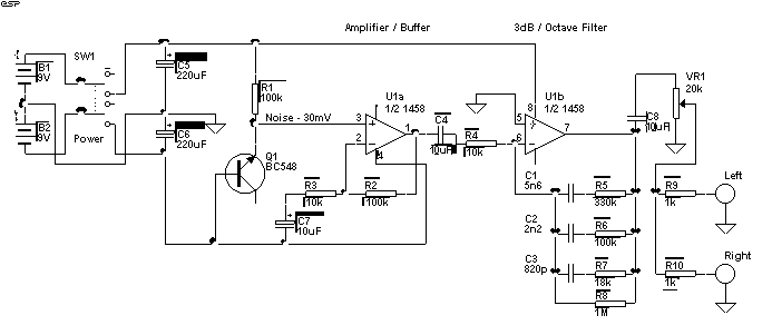
The bottom half of PAIA's plan shows the minimum-cost way to do it, if you buy vats of cheap NPN transistors. I do wonder if some of those coupling cap values are big enough. PAIA's synths were pretty funky and flavorful, and weak bass in the noise module would not be considered a flaw.
The plan Jakob posted, though hard to read, is the minimum-cost way now that an opamp is cheaper than a transistor. The output of U1a at the right side of C4 is white, you can omit U1b and all its crap if you don't need pink noise. Don't use the old 1458 chip: TL07x will slew faster and is easier to find today. This can run just as well on +15V, or +/-15V if you watch the cap polarity (C7 C4 will probably need to be reversed for >+/-7V).
As Adrianh says: the Maxim plan is good theory but the amplifier is aimed for 1MHz and up. For 10Hz-100KHz you want bigger coupling caps, and almost certainly a less-excitable amplifier.