SSLtech
Well-known member
As a spin-off from a thread in the Brewery, I thought I'd consolidate everything into a single 'Lab' thread...
So, here's a brief rundown on how to NEATLY wire snake cables to TT patchbays.
In this case, the cable is Mogami 24-pair shielded pair, and the patchbay is a Switchcraft 96-point TT bay. This particular patchbay example which I'm wiring doesn't call for any normalling, so no normalling is shown; -I'll try to take some more pictures and add them in with descriptions later on, next time I have to wire some more of those.
PREPARATION IS KEY.
If the prep is sloppy, the job will be sloppy. Take the time to prepare carefully and neatly, and the finished result will be all the neater.
First, you take some adhesive paper 'console tape' and lay it down on your patchbay, and mark the center position of each socket.
Like so:
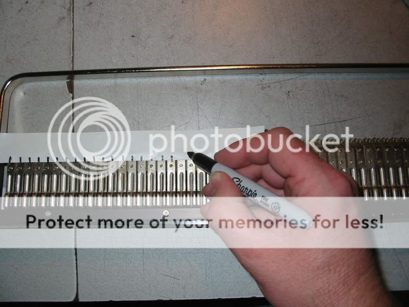
-Here's a close-up:
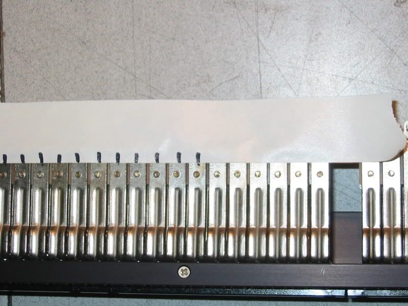
-Then you number the points...
like so:
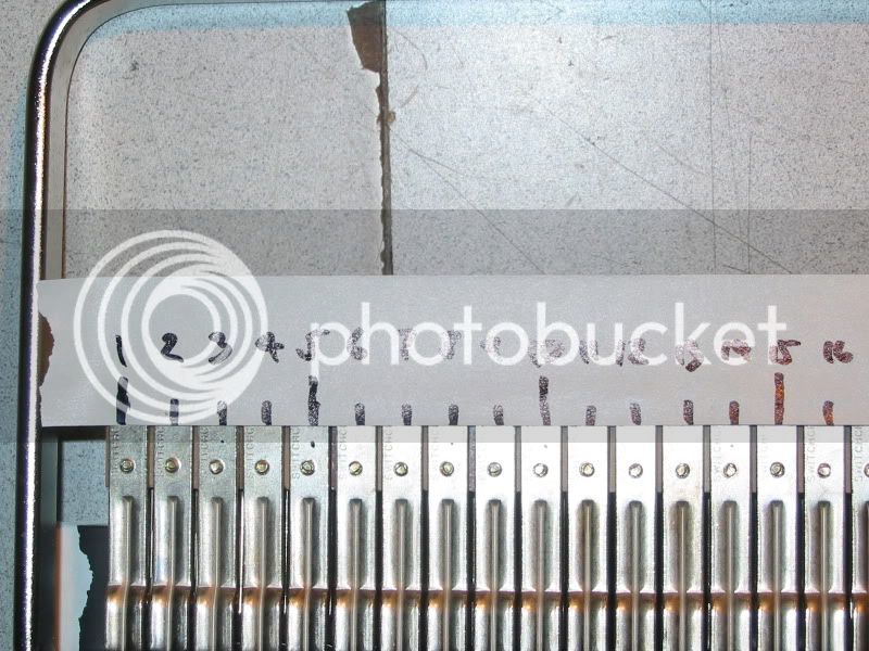
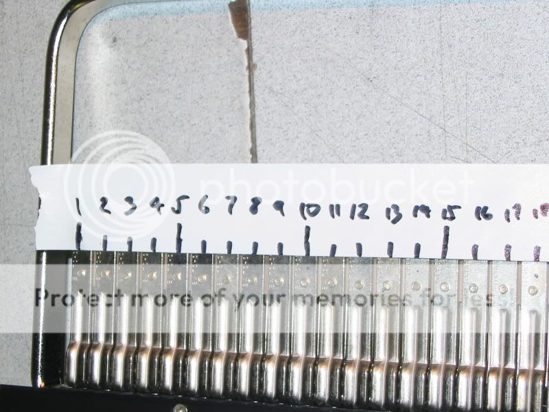
..Then you take your piece of marked tape, and use it as a cutting guide, to pre-cut your unsheathed and 'combed' pairs to length...
-Like so:
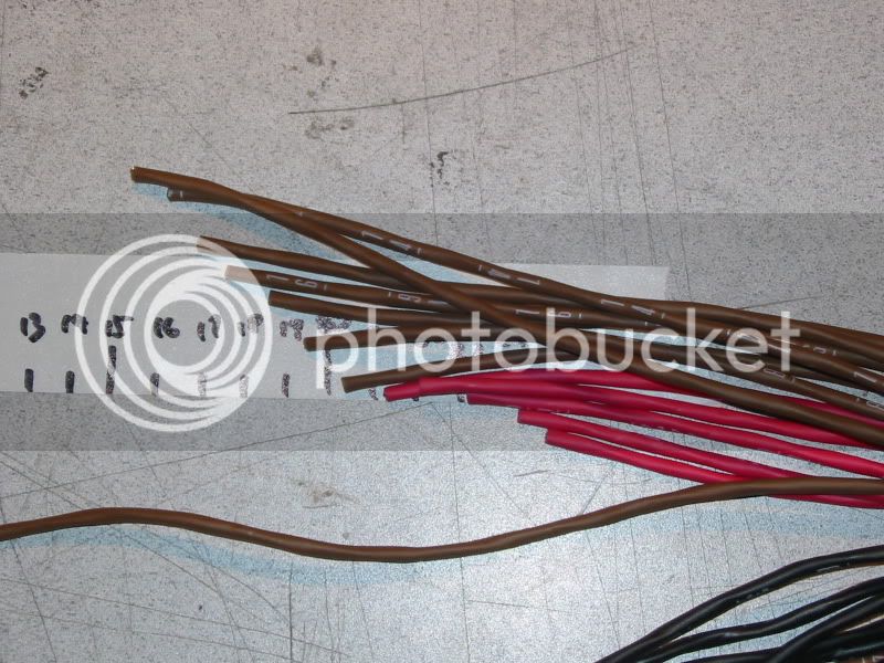
Continue doing this for all the snakes, Then once they've all been pre-trimmed to length, strip and tin the individual pairs, to a reasonably uniform length. I prefer about 18mm (3/4 inch) for the sleeve, and about 3mm (1/8 inch) for the conductors.
If the grounds are being kept individually isolated, then the drain wires should be sleeved leaving about the same 3mm length exposed, but in this case we're using a bussed ground, so the drain wires are simply tinned all the way back.
GROUND BUSSING
One of the nice things about Switchcraft solder patchbays are the 'offset' holes in the ground terminals, which allows you to thread a piece of buss wire from side-to-side, threading it through the 'eye of each ground terminal, like so:
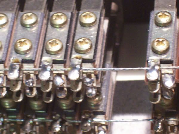
In this picture, I've also lightly splashed each of the ring and tip connections with some solder, to get things started, but the ground contacts are fully soldered to the ground bussing. (This is for inclusion in a new SSL console installation, and all SSLs have bussed grounds for everything except the mic lines.)
So now our patchbay is ready for attaching the wires:
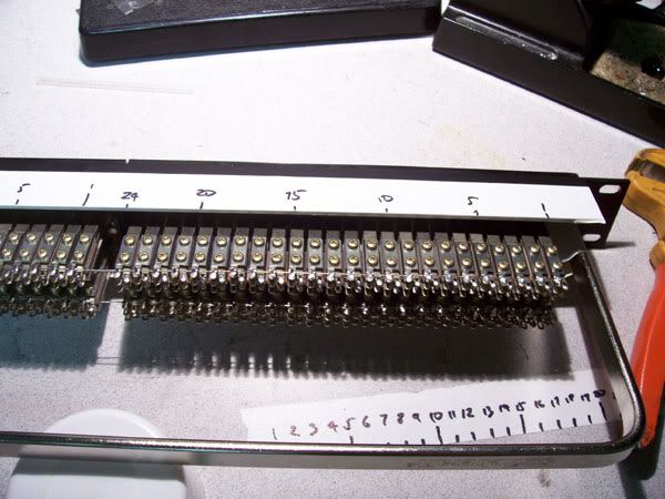
Start by attaching each pair, beginning at one end and working all the way to the other. -Take care to 'comb' the pairs out as you solder each one; make sure that each one is free from tangles all the way back to the overall snake jacket.
Use heat-shrink tubing for every connection... -EXCEPT the ground connections in a bussed-ground installation- and ensure that the tubing slides easily on after each solder joint has cooled. -In this instance I'm using clear heat-shrink tubing, so it's not easy to see, but everything except the drain wire is sleeved and insulated. -This makes any shorts or strand-bridges a practical impossibility, and pretty much eliminates the need to go back in and chase down problems afterwards.
Here's how it starts:
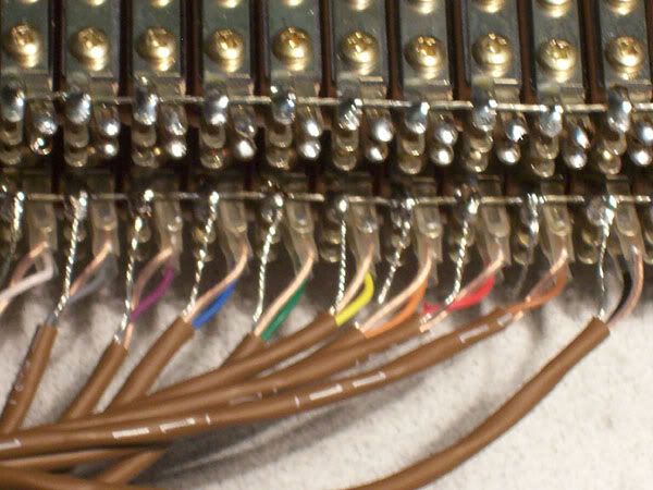
-And a zoomed-out shot a little over half-way through the first snake; this time from the other side:
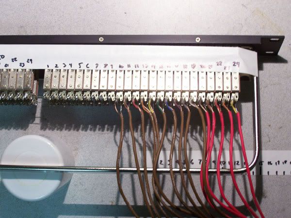
Here's the first snake all soldered-up. -Notice how the pairs all fall neatly and tidily to length:
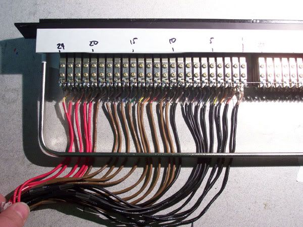
...and here's another shot after having attached a second snake to the adjacent row of sockets:
STRAIN RELIEF/DRESSING
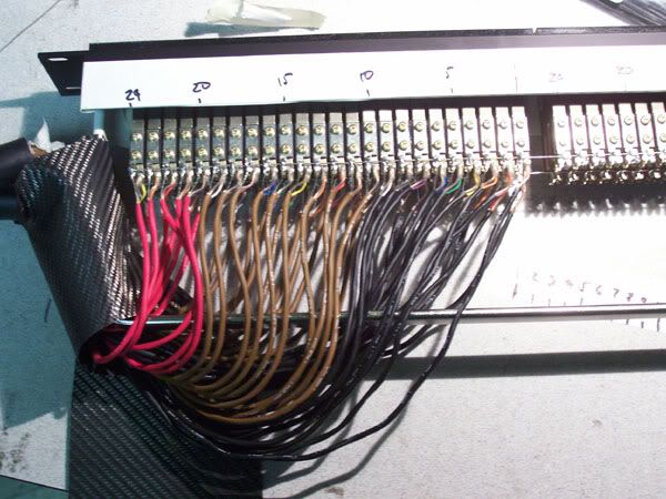
Take a little time now to slip on a few slim cable ties, and 'dress' the pairs neatly. Don't tighten them all up as soon as you put them on, slip them on loosely, and 'guide' the pairs into a nice tidy order as you go... only once they've started sitting perfectly neatly should you tighten them completely.
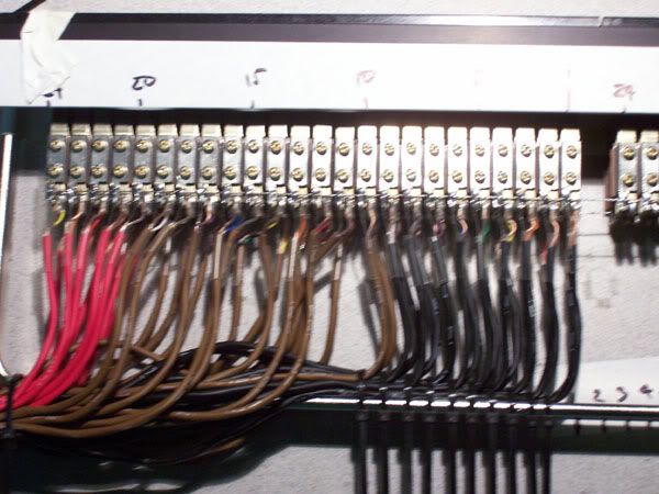
Here's the completed half of the patchbay after cable-tie dressing:
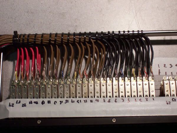
...and from another angle:
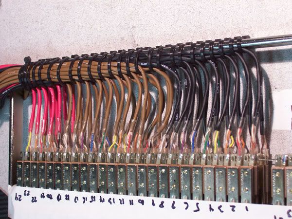
...So, from there on, it's just a question of repeating the process for the remaining half of the patchbay:
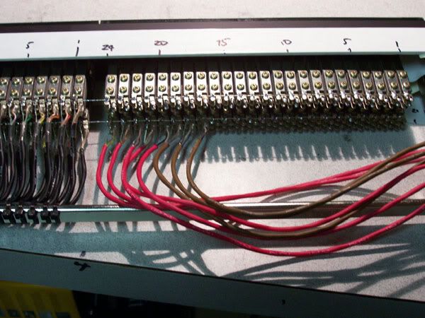
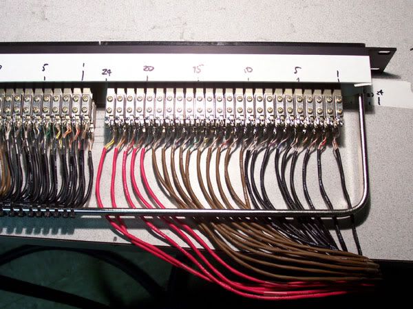
...the lower row complete, and strain-relieved while the upper row is started:
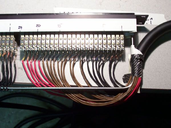
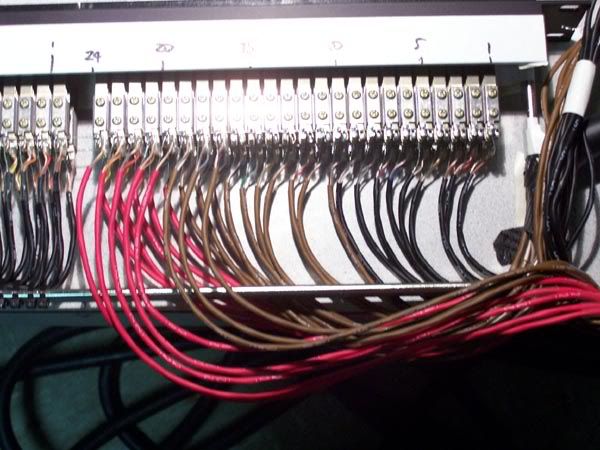
...the upper row completed and dressed/tied off.
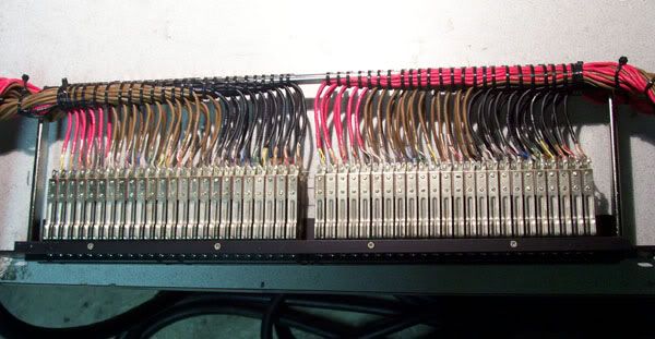
-A closer look at the finished job:
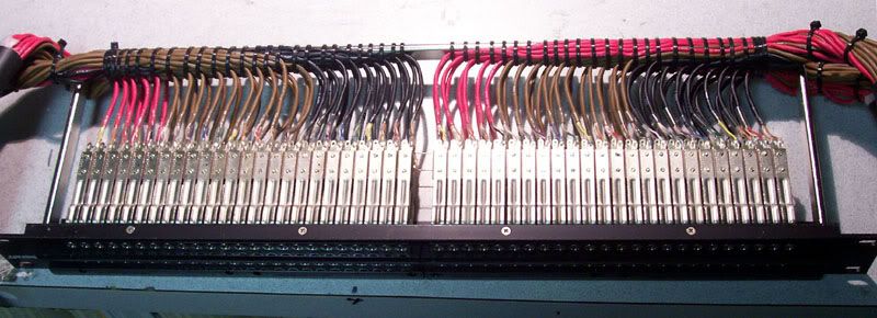
Some people (including myself) like to use lacing cord instead of cable ties. -It's a dying art, and something I'll occasionally do if there's NO possibility of anyone wanting to re-work the patchbay later. -If you're using this as a 'how-to' guide for wiring your first patchbays, now is probably NOT the time to attempt to learn how to use lacing cord... Start with cable ties, and -if you develop a perverse enjoyment from the 'Zen' of patchbay-wiring, then by all means look into it for the future.
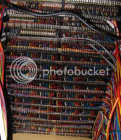
Here -once more- is the back view of a patchbay which I wired a few years ago:
Keith
So, here's a brief rundown on how to NEATLY wire snake cables to TT patchbays.
In this case, the cable is Mogami 24-pair shielded pair, and the patchbay is a Switchcraft 96-point TT bay. This particular patchbay example which I'm wiring doesn't call for any normalling, so no normalling is shown; -I'll try to take some more pictures and add them in with descriptions later on, next time I have to wire some more of those.
PREPARATION IS KEY.
If the prep is sloppy, the job will be sloppy. Take the time to prepare carefully and neatly, and the finished result will be all the neater.
First, you take some adhesive paper 'console tape' and lay it down on your patchbay, and mark the center position of each socket.
Like so:

-Here's a close-up:

-Then you number the points...
like so:


..Then you take your piece of marked tape, and use it as a cutting guide, to pre-cut your unsheathed and 'combed' pairs to length...
-Like so:

Continue doing this for all the snakes, Then once they've all been pre-trimmed to length, strip and tin the individual pairs, to a reasonably uniform length. I prefer about 18mm (3/4 inch) for the sleeve, and about 3mm (1/8 inch) for the conductors.
If the grounds are being kept individually isolated, then the drain wires should be sleeved leaving about the same 3mm length exposed, but in this case we're using a bussed ground, so the drain wires are simply tinned all the way back.
GROUND BUSSING
One of the nice things about Switchcraft solder patchbays are the 'offset' holes in the ground terminals, which allows you to thread a piece of buss wire from side-to-side, threading it through the 'eye of each ground terminal, like so:

In this picture, I've also lightly splashed each of the ring and tip connections with some solder, to get things started, but the ground contacts are fully soldered to the ground bussing. (This is for inclusion in a new SSL console installation, and all SSLs have bussed grounds for everything except the mic lines.)
So now our patchbay is ready for attaching the wires:

Start by attaching each pair, beginning at one end and working all the way to the other. -Take care to 'comb' the pairs out as you solder each one; make sure that each one is free from tangles all the way back to the overall snake jacket.
Use heat-shrink tubing for every connection... -EXCEPT the ground connections in a bussed-ground installation- and ensure that the tubing slides easily on after each solder joint has cooled. -In this instance I'm using clear heat-shrink tubing, so it's not easy to see, but everything except the drain wire is sleeved and insulated. -This makes any shorts or strand-bridges a practical impossibility, and pretty much eliminates the need to go back in and chase down problems afterwards.
Here's how it starts:

-And a zoomed-out shot a little over half-way through the first snake; this time from the other side:

Here's the first snake all soldered-up. -Notice how the pairs all fall neatly and tidily to length:

...and here's another shot after having attached a second snake to the adjacent row of sockets:

STRAIN RELIEF/DRESSING
Take a little time now to slip on a few slim cable ties, and 'dress' the pairs neatly. Don't tighten them all up as soon as you put them on, slip them on loosely, and 'guide' the pairs into a nice tidy order as you go... only once they've started sitting perfectly neatly should you tighten them completely.

Here's the completed half of the patchbay after cable-tie dressing:

...and from another angle:

...So, from there on, it's just a question of repeating the process for the remaining half of the patchbay:


...the lower row complete, and strain-relieved while the upper row is started:


...the upper row completed and dressed/tied off.

-A closer look at the finished job:

Some people (including myself) like to use lacing cord instead of cable ties. -It's a dying art, and something I'll occasionally do if there's NO possibility of anyone wanting to re-work the patchbay later. -If you're using this as a 'how-to' guide for wiring your first patchbays, now is probably NOT the time to attempt to learn how to use lacing cord... Start with cable ties, and -if you develop a perverse enjoyment from the 'Zen' of patchbay-wiring, then by all means look into it for the future.
Here -once more- is the back view of a patchbay which I wired a few years ago:

Keith


![Electronics Soldering Iron Kit, [Upgraded] Soldering Iron 110V 90W LCD Digital Portable Soldering Kit 180-480℃(356-896℉), Welding Tool with ON/OFF Switch, Auto-sleep, Thermostatic Design](https://m.media-amazon.com/images/I/41gRDnlyfJS._SL500_.jpg)

