zener shunt for psu

GroupDIY Audio Forum

Help Support GroupDIY Audio Forum:

This site may earn a commission from merchant affiliate links, including eBay, Amazon, and others.

seavote

Well-known member
Joined
May 31, 2006
Messages
1,085
Location
Breezy Point ,New York
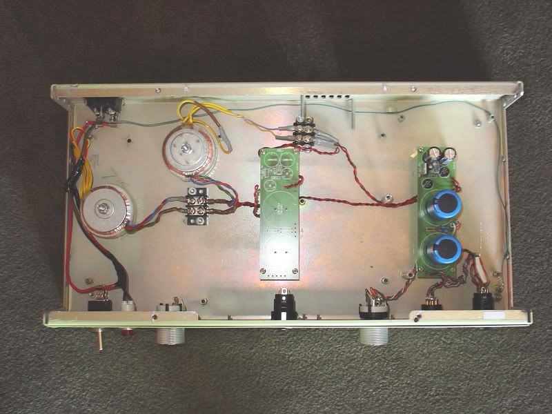
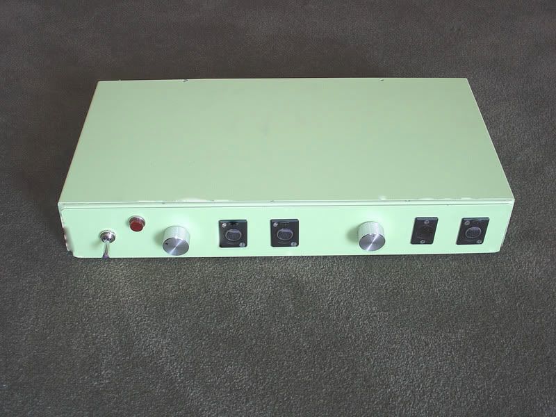
i'm building the royer mxl2001 tube mic mod. i want to mod a G7 tube mic psu to use for this project. the G7 B+V is 160. The royer needs only about !00Vs for B+. Schematics are here:
Royer
http://www.prosoundweb.com/recording/tapeop/tube_mic_25_3.shtml
Gyraf G7
http://www.gyraf.dk/gy_pd/g7/gic_s.gif

this is a plan i have but i dont know that it will really work the way i want to "cut and paste" it into the circuit:
http://i140.photobucket.com/albums/r34/seavote/zenershunt.jpg

the 20m will be a 20k and will replace the 10k resistor on the g7 psu . i've sourced 51V .5 watt zener diodes(in series to make 102V) and the 10k capacitor will be the existing 470Uf cap on the G7 schematic. i plan on wiring the diode between the 20k resistor and the 470uf cap (- side) on the underside of the pcb. i'm posting to check if this zener shunt is implemented correctly in this circuit. thanks for any suggestions, explanations ,theories etc. :cool:
 
Opamp Labs has a zener shunt reg calculator on their site. Here's the link: http://opamplabs.com/zenerreg.htm

If you are using the G7 power supply it would be easier to just use a different xfmr for the second one. Your two xfmrs would be 115:9v, then another one but reversed 9:115v. After rectification you would have around 160v without a load(actually it will be somewhat less depending on losses). Then you just need to adjust the resistor in the PI filter to get the correct votlage at the mic under load. This is how I've done it.

This is what I use for some of my mics that have a 5840 tube.

 
Just add another stage or two of RC at the B+ of the G7 supply,. Use ohms law

Current used by the plate circuit of the Royer will help you calculate the needed resistance to drop the voltage wanted. Voltage drop divided by the plate current will give the resistor value then calculate the power rating needed for the dropping resistor(s).

Need the stock Royer B+ and voltage at the plate of a Royer circuit 2001. Subtract the voltage at the plate from the B+ and divide that by the plate resistor for the current.

With a zener shunt reg you need to calculate the max current in the zeners with no load(microphone not connected) to calculate the power rating(s) needed of the series zeners.


The Royer power supply works well and uses one less transformer
 
thanks for the replies. big ugly, i'm building a dual power supply. G7 and royer. the G7 side is up and running. both sides will run off the same 2 transformers. the layout is already in place(both ps pcb stand offs drilled and ready to go.

Powersupplyinside.jpg


DualPowerSupply.jpg


so i'll go with gus's plan.
funny i had presented this way of acomplishing my goal(extra rc stage or 2) in a thread at tape op but was advised to use the zener shunt. i'll have to look at the layout to see where i should locate these stages. i believe i have plenty of room.
gus, one question, the plate current of the royer used to determine the resistor value is the plate current with the royer in the stock G7 psu?
 
The easiest thing to do would be to increase the resistor value in the G7 B+ to drop the voltage.

The harder thing to do is calculate using the G7 supply. It seems some that have built it have lower B+ voltages that the schematic shows.

So what I would do. I would built the G7 PS stock but use a 22K for the 10K between the two B+ filtercaps and measure the B+ under load. I would then adjust the value up or down as needed.

Yes the plate current is the plate resistor voltage drop(B+ - plate voltage) / the plate resistor
 
thank again for all your help gus. My G7 psu runs at the full 160V ...well usually 157 -159.while i was having trouble with my build i recorded a test vocal. the voltage was only about 120V and there was a hum present in the signal. i was blown away by the quality of the audio(hum not included). while my G7 sounds great now there seems to be an unflattering bump in the high mids that can show itself depending on how the singer works the mic. (same room,same position in room,same singer,me)i didnt recall this at all at the lower voltage so i hooked up 2 10K resitors in series to see what voltage i would end up with. i dont remember the exact number but this increase in resistance only brought the voltage down to about 150V.
is there a limit, a top resistor value, i can use befor there will be detrimental effects to the audio quality or stability of the circuit? in order to drop the voltage to near 100Vs i would think(not that i know) this resistor value would have to be quite larger than the original 10k.
 
47K resistor got me 120V exactly(on my G7 mic). the first value i tried. mic does sound smoother.no more high mids bump. its a carbon resistor so when i get around to it i'll order a metal film. i'll 60somethingK (i'll see what i can come up with from what i have)for the royer mod and go from there. thanks gus
 
Since I have a few standard Chinese power supplies running at 120V / 6V, I'm thinking of building mics to use these same supplies and have them adjust the B+ internally.

Does it seem reasonable if I want to lower B+ in the mic to just drop it via a potential divider? I'm looking to drop to around 24V, but with larger values I shouldn't be producing too much heat.

The other alternative I considered was a diode regulator, but since the supply is regulated, I don't really see the point since it will add noise also.
 
Back
Top