


Can someone explain the "zero impedance output" circuit in Small Signal Audio Design by Douglas Self page 426?
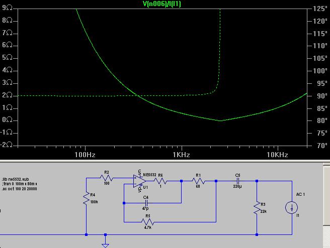
More specifically, I would like to model this circuit to understand why it supposed to be "not affected by load capacitance" as described on page 382.
Is it not possible to model this performance improvement in LTSpice?
More specifically, I would like to model this circuit to understand why it supposed to be "not affected by load capacitance" as described on page 382.
Is it not possible to model this performance improvement in LTSpice?