11 Slot DIY API 500 series rack

GroupDIY Audio Forum

Help Support GroupDIY Audio Forum:

This site may earn a commission from merchant affiliate links, including eBay, Amazon, and others.
[silent:arts] said:
main thing:
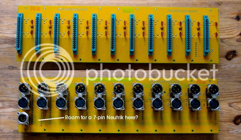
the 51x 18pin Racks need an internal PSU, unless Neutrik releases a 7 pin PCB mount XLR  ;D
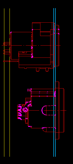
I fear the first batch of the shown prototype case is only 15pin compatible.
this will need a PSU too, but can be done external.


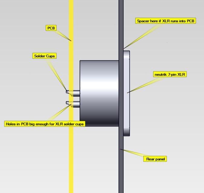
Why not just use a 7-pin, panel-mount neutrik with solder-cups like this:
http://www.neutrik.com/us/en/audio/210_t3_1667453931/NC7MD-LX_detail.aspx

You would have to wire it manually, but the rest of the connectors can remain PCB-mount.

If there's not enough space between the back of the neutrik connector and the backplane PCB, then just use a spacer of some sort to elevate the connector from the panel to provide a little more space.

You could solder short, solid-copper wires into the solder cups, essentially converting it into a PCB-pin version.
OR, you could just make the holes in the PCB large enough to accommodate the solder cups on the 7-pin neutrik connector.


Hi Skylar,

nice suggestions, now it comes back to DIY  ;D ;D ;D

the backplane PSU XLR connector is 16V only, pin compatible with any API compatible PSU.
there is a Molex connector too, with the two added voltages.

anybody is free to use whatever fits, and your suggestions sound good.
but I'm not into mechanics ...
 
Here's what I was talking about.
It's a little easier to explain with a picture.

51X_7p_XLR_mockup.jpg


So, you're saying the reason not to use a 7-pin is because we want these to work with API-compatible power supplies (which use 5-pin).

I guess my question is...who is NOT going to DIY their own power supply?

Anyway, it looks like there's room to allow usage of a 7-pin AND/OR the existing 5-pin.
This way the builder can drop in either a 7 or 5 pin neutrik or both!
51X_7p_XLR_mockup2.jpg


Also, do you have any high-res images of the boards or a pdf, etc?
It would be nice to see how the board is laid out...pin-outs and such.


EDIT: before I get flamed...I have already seen this: http://www.51xaudio.com/51x_pinout.html
When I say pin-outs, I'm talking about the Molex header/jumpers and stuff.
 
3nity said:
looks good!!
has anyonw look at this?

The benefit of having something handwired over a pcb is that if you plug and unplug something too many times, the circuit board traces can break. When its handwired the wire flexes so this will never be a problem. Also this makes repinning a breeze as you just move one wire after another. Not possible on a circuit board.


3nity,

Our PCb is 3mm thick and supported by 22 stand-offs plus 23 neutric connectors with 46 screws. I can assure you, you will need to run a truck into this board to damage the tracks.  


Skylar,

Good idea. On the production runs I will include the aperture for the additional Neutric power connection as an option.
 
[silent:arts] said:
Biasrocks said:
I know this is late in the game, but termination resistors are
This is a crucial feature which changes the sound of the modules and should be included on the back plane PCB IMO.

but soldering termination resistors on the backplane doesn't give you the freedom of exchanging modules as you might want. I would still do this on in the module if needed, or in the outgoing XLR connector.
anyhow, it is still possible doing it directly with the backplane.

Exchanging modules is not a priority for me and I'm not sure if it's a priority for many people, if I did need move something into a position that had been terminated, removing a resistor from the backplane is not a big deal. All API modules need termination, even though I suspect many are being run without proper termination. Other VPR modules may or may not; for example, many of the Neve type VPR modules I've seen do not provide termination within the module, aside from Dan Kennedy's Neve type modules and definitely require termination to operate within spec.

It looks like there's room to solder a resistor across the output XLR pins on the backplane, as opposed to offering a resistor soldering point. Is this what you suggesting as a solution?

Mark
 
Skylar, I like your idea very much.
you see the solder pats where you want to place the seven pin Neutrik ?
this is exactly the molex connector.
doesn't matter, can be anywhere (in the row).

I hope this doesn't end in don't having a case without internal PSU ::)
(since that is what I want)

however, the 5 pin PSU XLR I use is:
http://www.neutrik.com/us/en/audio/210_2116229466/NC5MBV_detail.aspx
gives 24mm inside space between the PCB and the back metal work.
your suggestions could work, have to look deeper in it.
 
Biasrocks said:
... Exchanging modules is not a priority for me ...
... All API modules need termination, even though I suspect many are being run without proper termination ...
Mark,
I don't think the majority of modules put into this racks will be original API.
terminating at the backplane will result in even more wrong terminated modules.

since the target is more to have a frame for our very own build modules termination at the backplane is unnecessary IMHO.
 
Is it a big deal to include termination resistors on the backplane and have dip switches to enable/disable them?

---Joe

[silent:arts] said:
Biasrocks said:
... Exchanging modules is not a priority for me ...
... All API modules need termination, even though I suspect many are being run without proper termination ...
Mark,
I don't think the majority of modules put into this racks will be original API.
terminating at the backplane will result in even more wrong terminated modules.

since the target is more to have a frame for our very own build modules termination at the backplane is unnecessary IMHO.
 
Yeah, I made the bold assumption that the termination resistors would be 600 ohm, and the DIP switches would switch them in/out.  I guess you could come up with a ladder scheme that would both minimize the number of DIP switches/resistors and still give you all those different termination values, but that sounds like too much work to me :)

---Joe


bahrens said:
[silent:arts] said:
joe-electro said:
Is it a big deal to include termination resistors on the backplane and have dip switches to enable/disable them?
you mean to select the termination to 200R, 600R, 1K2, 10K and 100K ?

It sounds like he meant either terminated or not..
 
bahrens said:
[silent:arts] said:
joe-electro said:
Is it a big deal to include termination resistors on the backplane and have dip switches to enable/disable them?
you mean to select the termination to 200R, 600R, 1K2, 10K and 100K ?

It sounds like he meant either terminated or not..

That would be ideal, insert the resistor value of your choice and have it switchable in/out with a jumper.

I would be happy to just have a couple of pads across the output to solder a resistor and have termination permanent for that slot.

Mark
 
Hmm. I was under the impression that API mic pre's in fact did not need termination, and that Neve modules only did with long cable lengths.
 
desol said:
Hmm. I was under the impression that API mic pre's in fact did not need termination, and that Neve modules only did with long cable lengths.

It's for proper loading of the output transformer, without it the Neve and API transformers do not perform to spec. All of my API and Neve modules are terminated, it does make a noticeable difference to the sound of the modules. Some people prefer the Neve's without termination because it adds a certain HF enhancement/distortion from the ringing transformer. Dan Kennedy included a loading switch on his GR-Neve channel for that exact reason.

There's a often quoted story about Geoff Emeric complaining that some of the modules in his newly delivered console were brighter sounding. When Rupert measured it he found a bump up around 40kHz or 50kHz! It turned out that the suspect modules weren't terminated correctly.

Mark
 
I have heard that story too. Apparently it was due to cable capacitance, hence terminating with appropriate resistor makes sense.

However, I am still trying to understand how a peaking pushed well beyond the hearing level can make such audible difference. But that is another story. May be somebody starts a new thread and gives his/her experience.
 
Hmmm.  I heard that story too, only the version I heard said the root of the problem was poorly grounded input transformers. Wonder which is correct?

---Joe

Biasrocks said:
There's a often quoted story about Geoff Emeric complaining that some of the modules in his newly delivered console were brighter sounding. When Rupert measured it he found a bump up around 40kHz or 50kHz! It turned out that the suspect modules weren't terminated correctly.

Mark
 
joe-electro said:
Hmmm.  I heard that story too, only the version I heard said the root of the problem was poorly grounded input transformers. Wonder which is correct?

---Joe

It was the termination resistors, at least, that's how I heard it from number of reputable sources. I've looked at this on a scope before with a Great River NV. The ringing is around 50K. I've also used the loading switch on my MP-2NV a number of times, and I can almost always tell the difference (depends on the source). I'm not hearing the 50K, I'm hearing the slight rise in the high frequency that leads up to the ringing at 50K. It can make a surprising difference.
 
sahib said:
... Good idea. On the production runs I will include the aperture for the additional Neutric power connection as an option.

good news: no need for it:

XLR7.png


mounting the 7pin XLR from the outside gives enough space for running cables to the Molex connector.
the stock 5pin XLR hole can be used.
 
[silent:arts] said:
the stock 5pin XLR hole can be used.

The A or B series PCB connectors (that you are using according to the photo) have different panel cut out than the 7-pin NC7MD.

(I understood the situation so that you are replacing the 5-pin PCB connector with a 7-pin wired connector.)
 
audiox said:
[silent:arts] said:
the stock 5pin XLR hole can be used.

The A or B series PCB connectors (that you are using according to the photo) have different panel cut out than the 7-pin NC7MD.

(I understood the situation so that you are replacing the 5-pin PCB connector with a 7-pin wired connector.)

ouch - after checking the pdfs again this is sadly true  :-[
 
Back
Top