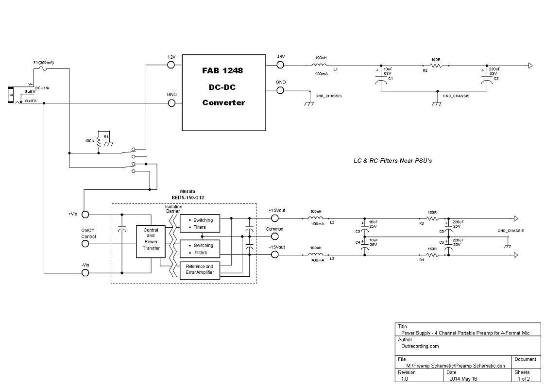
Looking at values, you need to be concerned about the RC filters and voltages.
There are some large drops across the Resistors R2, R3 and R4.
The corner frequency for 150R/220R is about 5hz, so that is ok, well out of the audible spectrum.
Phantom:
But if you draw 56ma (14*4) through R2 you will drop 8.4 Volts. Of course you will never draw that much except if you short all the phantom power to ground. Typical is 4-7ma per mic or less, more if there is an LED or for some DI's. So engineering for 24mA should be fine, and the voltage drop would only be 3.6V.
You can solve the issue in various ways.
0) ignore it, because you are still getting 44V which is fine for all phantom power mics
1) increase the voltage output by the FAB1248 to 53V or 54V
2) reduce the value of the resistor increase the value of the cap. For instance use a 1000uF cap with a 33R resistor. Same corner frequency, much lower voltage drop.
3) put separate filters on each mic connection. This can keep things low profile (because the components are smaller) but probably takes more space overall. It depends where you have space.
Most phantom power mics will run on a broad range of voltages, 52V is usually the max spec'd but some will run on very low voltages down to 12V or 18V etc. However as the voltage falls the maximum signal level handling of the mic head preamp so if you intend very high SPL usage then use a low current mics or modify the filter for less voltage drop.
I would choose quiet stable phantom rail over maximum voltage.
I rarely mike loud guitar amps, and in an ambisonic mic you would never close mic anything to my understanding (they are for free field kind of use right?). So lower phantom voltage is not a big deal.
You can also do less filtering, especially if this will always be run on battery then the likelyhood of low frequency (50hz or 60hz) noise is much reduced. So you have good filtering on the HF end (where the SMPS is making the noise) and you could raise the corner frequency.
As for R3 and R4, I think there the voltage drop is a big issue. You are getting a load of 120ma, and across a 150R resistor that is too much drop (150 * .120 = 18V drop). So you need a bigger cap and a lower value resistor. But you can use low voltage caps which are smaller, so this should not present a size problem. So for instance you could output 16V and engineer for a 1V drop 1/.120 = 8.3R... so use a 10 ohm resistor with 3300uF or LESS (because eden and other opamp based amps are good at common mode noise rejection they DON't NEED power to be as quiet). There are several, they are not that big. Here is a 3300uf search in mouser
http://www.mouser.com/Passive-Components/Capacitors/Aluminum-Electrolytic-Capacitors/Aluminum-Electrolytic-Capacitors-Leaded/_/N-75hqw?P=1z0x6edZ1z0wrk0
You may have to experiment with fuse value depending upon how the DC-DC converters behave as they charge the caps, or slow blow fuse.
That on off control looks unconnected.
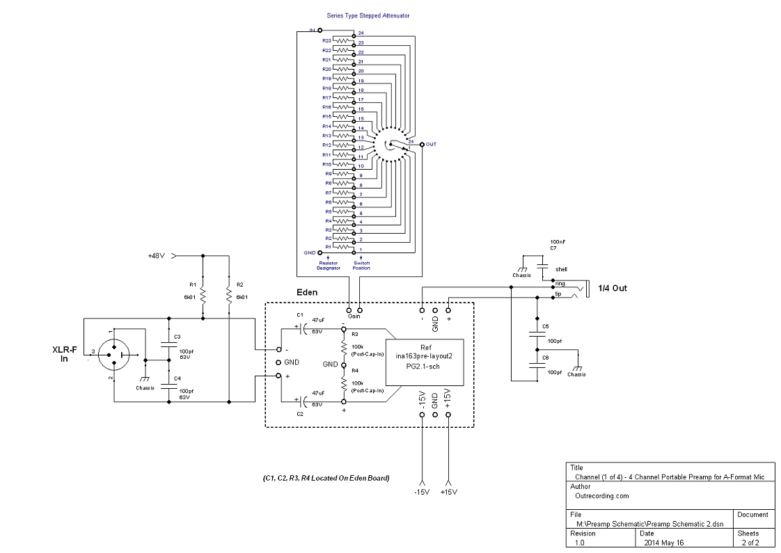
On the channel
You do have the opportunity to make the switched resistor in a different style. This way at high resistances you have many resistors in series. This tends to make a larger path (loop of wire) and each resistor has some noise.
This will be totally fine, and is very common and I have done it that way too.
But you should be aware that in your case you can also just use a single resistor in each switch position. To a common conductor that goes to the gain connection on the eden (the other goes to the switching side of the switch).
Also, I am not sure you want that Ground near R1 on the switch, it should be open, (actually as drawn it is shown as open , but it says ground so I thought I would mention it).
The other R1 and R2 (6K81) should be selected carefully to be matched as close as you can achieve. Using a DVM gets you much closer than 1%.
The schematic is great thank you, and allows very detailed comments (as you can see) I hope they are helpful.
One important thing on a schematic. Each page should only use a named designator once. Better in a whole design each designator should be used only once (for instance on sheet 1, resistor 1 should be R101 and on sheet 2 resistor one should be R201). Keep on that way till you design something with 10,000 components in it, and then you can solve it another way.
That way when I say R1, I am referring only to a single resistor. In this schematic I am referring to at least 3!
b


") however, there are external ESD protection diodes on the inputs, to protect from such surges. (having been burning by 48V surges)/
however, there are external ESD protection diodes on the inputs, to protect from such surges. (having been burning by 48V surges)/