4 Channel Portable Ganged Gain Mic Pre with Eden Preamps for Ambisonic Recording

GroupDIY Audio Forum

Help Support GroupDIY Audio Forum:

This site may earn a commission from merchant affiliate links, including eBay, Amazon, and others.
You mention increasing the output by one volt. How can I do this without taking up a lot of space? N

Just use larger value cap and smaller resistor value, won't take much space .

Didn't know you already had the converter in hand

Or don't worry about the 1 volt, it will work fine at +- 14 too. Small loss of headroom which is not an issue for you.

 
Here are the revised schematics. I've searched locally for parts and some of these values reflect what's available to me. There are a few numbers I'm uncertain if they're too low/high. Specifically:

C10/C11 - Can I get away with 50V here?  For 100pF I can find a plethora of 50V and WAY higher volts, but no 63V.

(C12/C13 - 50V prob too high, but I can't find anything lower)


With the grounds, I'm probably drawing too literally (copying Ricardo's recommendations). But seems good for my brain to see them how they should be.


Preamp_V1.1_pg1.png


Preamp_V1.1_pg2.png
 
One specific grounding question for Ricardo....

For C12/13/14 and output sleeve, where are these physically grounded?

I recall you mention they'll have their own grounding point, but I can't seem to find that you ever said that in this thread. Maybe I dreamed it up. Would these also then go back to the input chassis connection?
 
bruce0 said:
You mention increasing the output by one volt. How can I do this without taking up a lot of space? N

Just use larger value cap and smaller resistor value, won't take much space .

Didn't know you already had the converter in hand

Or don't worry about the 1 volt, it will work fine at +- 14 too. Small loss of headroom which is not an issue for you.

Yeah, my folks sent some stuff out for my son's birthday and I figured I could save some shipping cash if they threw in some parts. The Murata was one of them.
 
outrecording said:
For C12/13/14 and output sleeve, where are these physically grounded?
On each TRS socket, these caps should have the shortest possible leads and connect to the CLOSEST CHASSIS POINT.

The idea is to get any RFI to the chassis as soon as possible with as little flow within the box.
______________________

There's never a problem if cap. voltage rating is too high.  For electrolytics, a higher voltage rating usually gives you better ESR too.  Voltage ratings for caps are usually conservative .. EXCEPT FOR ELECTROLYITICS.
______________________

'twisted' refers to the leads from the SMPSs to the rest of the circuit.  eg +/-15V and its COMMON are twisted and go to Eden +/-15V GND  ..  NOT to the i/p or o/p GNDs
 
ricardo said:
outrecording said:
For C12/13/14 and output sleeve, where are these physically grounded?
On each TRS socket, these caps should have the shortest possible leads and connect to the CLOSEST CHASSIS POINT.

The idea is to get any RFI to the chassis as soon as possible with as little flow within the box.
______________________

Ok, glad I didn't dream that up. Would you recommend the caps on these four outputs all go to a single point (between ch2/3 most likely) or literally each set of caps will get its own chassis connection? Taking literal meaning of the "Closest Chassis Point".

ricardo said:
There's never a problem if cap. voltage rating is too high.  For electrolytics, a higher voltage rating usually gives you better ESR too.  Voltage ratings for caps are usually conservative .. EXCEPT FOR ELECTROLYITICS.

Thanks
______________________
ricardo said:
'twisted' refers to the leads from the SMPSs to the rest of the circuit.  eg +/-15V and its COMMON are twisted and go to Eden +/-15V GND  ..  NOT to the i/p or o/p GNDs
Thanks. I got a lot to learn.  :)
 
A couple random questions I've been holding on to:

- Shielded cable - Yay or Nay?

I have some stranded cable with two twisted wires inside covered by braided shielding. It could be used for both signal and/or power. It isn't twisted nearly as much as I believe it should, but maybe that's partially negated by the shield. Would this be a viable alternative to using unshielded wiring?

- Attaching standoffs to the case

Being that this will be portable, I'd really like to NOT drill holes and have screws sticking out the bottom. Is there any practical way around this? Would using epoxy (for example) be a bad idea to seat the standoffs?
 
The shield is for EMI (high frequency).  If you have a metal case given the runs it probably is not a great benefit internally.  If you do use it connect the shield to ground on only ONE end (avoid creating secondary ground paths).

Nice countersunk holes are secure, and don't look bad. People do use glue, some use a metal glue if they want grounded standoffs. But if you do I would put something in to support the board to the other side of the case (little block of foam or something, not on top of anything that needs cooling).  There are pre-made standoffs with double stick tape and large footprints... I have had them come off (thus the foam block).
 
outrecording said:
Ok, glad I didn't dream that up. Would you recommend the caps on these four outputs all go to a single point (between ch2/3 most likely) or literally each set of caps will get its own chassis connection? Taking literal meaning of the "Closest Chassis Point".
No.

The caps must go to their individual nearest chassis connection point with the shortest possible leads.  1" is way too long for this.  Some XLR sockets have dedicated pins for a chassis connection (usually to allow p1 to be connected or not to the chassis) and also ensure the XLR socket body is well connected to chassis.
 
Hi guys! I'm back! It has been a while...

I got side tracked with another project and then my ambisonic mic broke.  :(  $500+ later in shipping and warranty repairs and it was fine for a bit. Then developed another prob. Long story short, I put this preamp on hold til I could figure out what was wrong with the mic. Tried the mic the other day after a reminder from Rochey and it's completely fine. Ok then....

I started working on the PSU and encountered a problem. My soldering skills could use much improvement but after double, triple, quadruple checking, I was satisfied all looked well. Tested it with fingers crossed and nothing exploded. ;) Half expected that to happen.

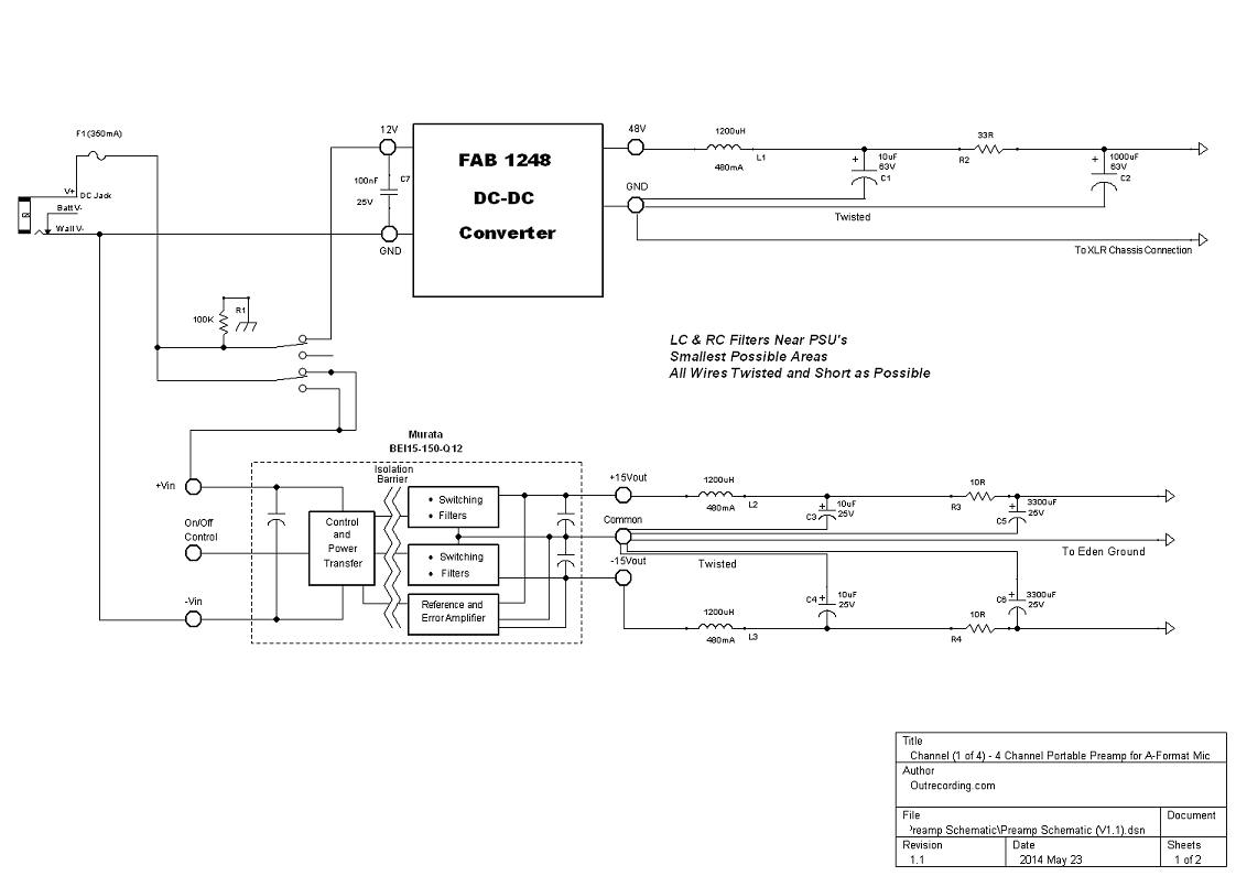
48V came out to damn near 48V. Excellent there. But the 15V was around 6V. Shortly after the measurement R3 and R4 started smoking.  :-\ 

Does that mean that the 10R is too small? Or I've read that a smoking resistor could mean a short downstream. If it were one resistor, I would think that. But both...I'm guessing they're too small?

Would you mind looking at the schematic above again? I'm worried I may have gotten a capacitor backwards or something (C3, C4, C5, C6) I've got them wired per schematic. Just double checking.

I'm planning to put this into a temp case I found at an electronics store. Got a small one and a larger one. I don't want to have one made and find out I'm getting noise cuz everything's too close.

Glad to be back!
 
So it sounds like the issue with the power supply board? I don't have your order details on my phone, but it sounds like your using the uber psu.

Step 1 - disconnect the output
Step 2 - measure the resistance between the outputs and gnd on the uber psu

Now do the same on your edens
 
Rochey said:
So it sounds like the issue with the power supply board?

Ah no, I didn't get your uber power supply. So all good on that front. :) Using a Murata followed by LC and RC Filter.

 
I pulled the burnt resistors and measured up to that point and getting about 15V. I'll double check my connections and try putting some larger resistors in there and see what happens.
 
My bad. I see it now. R2 and R3 are on the power supply schematic.

Looks like you have a short on your PSU outputs.

Please check your +15V to 0V impedance on your edens, same for -15V to 0V. (I think you got a 4 pack, try each)

Also,let me know if the INA163 is getting warm on the eden. It may be a sign of oscillation.

Cheers,

/R
 
Actually I haven't connected the PSU to the Edens yet. Since this is my first foray into preamp building I wanted to make sure I was getting correct voltage and all was well with the PSU before moving forward. perhaps that's the issue? Needs to be something connfted to the PSU? With nothing there, something's gonna burn up? (Though 48V is ok . So maybe not)

Rochey said:
My bad. I see it now. R2 and R3 are on the power supply schematic.

Looks like you have a short on your PSU outputs.

Please check your +15V to 0V impedance on your edens, same for -15V to 0V. (I think you got a 4 pack, try each)

Also,let me know if the INA163 is getting warm on the eden. It may be a sign of oscillation.

Cheers,

/R
 
Figured out my error. MY error.  :eek:  Mixed up my positive and negative rails. Caps all backwards. Good to go now and on to the rest.
 

Latest posts

Back
Top