4 Channel Portable Ganged Gain Mic Pre with Eden Preamps for Ambisonic Recording

GroupDIY Audio Forum

Help Support GroupDIY Audio Forum:

This site may earn a commission from merchant affiliate links, including eBay, Amazon, and others.
Rochey said:
I would have thought that not connecting to the input GND from the XLR is important... as you don't want stray current from the shield and from the case straying into your circuit.
In my recommended system, the star point is at the input.  Connecting shields (p1) to the chassis directly means anything on the shields stays outside the 'Faraday cage'  The star point is the 'reference'.  The problems occur if the shield currents have to flow along a little aerial to get to the 'Faraday cage' (chassis) .. or worse, through Eden's ground plane.

As the 48V is handled offboard, I'm struggling to get my head around the current flow of the phantom power.
That's why I've re-drawn the earthy end of the filter caps recommended by Bruce.  All the SMPS currents are limited to the P48V.  (this is the intensively filtered offboard stuff)  The 2 twisted P48V wires coming from the FAB1248 should not have any SMPS stuff including decoupling current.

The P48V 'GND' of this twisted pair is connected to the input star point (p1) so the mike P48 current goes directly back to it.  Any cr*p left on that supply doesn't flow through any part of Eden. (this is the starred back to the same place as your eden psu-ground)
________________

Alas, you can't do the same for +/-15V cos of the earth plane and the 10u caps on the supply.  The +/-15V 'Commons' is connected to Eden +/-15V GND cos that's what you said is the closest GND to the 10u caps.
________________

The only thing I'm not sure about is whether or how to decouple the 12V inputs to chassis.  :-\

 
The only thing I'm not sure about is whether or how to decouple the 12V inputs to chassis.  :-\

Taking a look at the application notes for the 12/15 supply, it is isolated.  I think it is totally floating not decoupled with a cap.  Decoupled in that it is not coupled at all.

I don't know, but would hope, that the FAB thing is isolated too.

This thing runs off 12V.  It is bound to be plugged into a cigarrette lighter at some point.  That is nasty power, isolated is nice.  Whether there or connected to a battery in his luggable case, either way the 12V does not provide a safety ground, so why couple it at all?
 
bruce0 said:
You may have to experiment with fuse value depending upon how the DC-DC converters behave as they charge the caps, or slow blow fuse.

That on off control looks unconnected.

Yeah, I'm thinking the fuse might be too small. You recommended 500mA I believe. Will trial and error this part.

For the on/off control, I was reading the below to mean that it's an optional feature (that I wouldn't need?)

"For systems requiring controlled
startup/shutdown, an external remote On/Off
control may use a switch, transistor or digital logic."


bruce0 said:
Also, I am not sure you want that Ground near R1 on the switch, it should be open, (actually as drawn it is shown as open , but it says ground so I thought I would mention it). 

Thanks for noticing that. That ground needs to go somewhere.

And this portion of the schematic is for the Goldpoint attenuator I found on their website.


bruce0 said:
The schematic is great thank you, and allows very detailed comments (as you can see) I hope they are helpful.

One important thing on a schematic.  Each page should only use a named designator once.  Better in a whole design each designator should be used only once (for instance on sheet 1, resistor 1 should be R101 and on sheet 2 resistor one should be R201).  Keep on that way till you design something with 10,000 components in it, and then you can solve it another way.

That way when I say R1, I am referring only to a single resistor.  In this schematic I am referring to at least 3!

b

Thank you for the feedback. I'll have a look at a new store I found locally to see what they carry. Mouser is around $30 a shipment to here; free if I buy $100 or more. Don't think I need that many resistors and caps!  ;)  I'll adjust some of the values you mentioned based on what I can find.

I'll work on new schematics based on the feedback I've received - including schematic name designation. :)
 
ricardo said:
outrecording said:
I don't have a chassis ground on the Eden yet. There are technically four grounding points (after putting the 100k to Post-Cap ground; although according to the Eden schematic, the input and Post-Cap grounds look to be connected?)

I'm unsure if I should just be grounding from one place or all of them to chassis?
Recommendations attached.  This is a PHYSICAL wiring recommendation too.

Not ideal but forced by Eden's ground plane.

Think about restricting all SMPS currents to the PSU. 
Hence the wiring of the filter caps directly to the SMPS pins and all wires twisted.
Don't duplicate your switch to the SMPS cos that makes the LOOPs bigger.

P48V is earthed to the XLRs so its current never appears on Eden earths.
+/-15V to Eden's GND cos that pin is closest to Eden's 10u caps

You need to be very specific about naming your earths and where they are connected.

Ah! Thanks for drawing that. I misunderstood what you wrote about where the dirty and clean earths should go.
You're saying in the schematic I need to name each earth and where it goes (i.e. chassis at input, chassis at output)?
 
bruce0 said:
This thing runs off 12V.  It is bound to be plugged into a cigarrette lighter at some point.  That is nasty power, isolated is nice.  Whether there or connected to a battery in his luggable case, either way the 12V does not provide a safety ground, so why couple it at all?

I can honestly say it will never see a cigarette lighter. When I'm out recording I drive my scooter (main mode of transportation here...heck, it's 125cc...not toounmanly, right?). Although if someone fancied to use the design for their own preamp, maybe it could be an issue.
 
outrecording said:
For the on/off control, I was reading the below to mean that it's an optional feature (that I wouldn't need?)

"For systems requiring controlled
startup/shutdown, an external remote On/Off
control may use a switch, transistor or digital logic."

Yes that's fine.

bruce0 said:
Also, I am not sure you want that Ground near R1 on the switch, it should be open, (actually as drawn it is shown as open , but it says ground so I thought I would mention it). 
Thanks for noticing that. That ground needs to go somewhere.

And this portion of the schematic is for the Goldpoint attenuator I found on their website.

I think that is wrong.  You want the switch to be ungrounded.  It is simply a variable resistor as called for by the Eden (I believe, haven;t looked at the eden stuf in a while).  Grounding it would cause problems.

I was worried that you INTENDED to ground it.  Don't ground it. 

In some schematics it would be labeled N/C no connection in some schematics it would not be there at all.


Thank you for the feedback. I'll have a look at a new store I found locally to see what they carry. Mouser is around $30 a shipment to here; free if I buy $100 or more. Don't think I need that many resistors and caps!  ;)  I'll adjust some of the values you mentioned based on what I can find.

I'll work on new schematics based on the feedback I've received - including schematic name designation. :)
 
bruce0 said:
Taking a look at the application notes for the 12/15 supply, it is isolated.  I think it is totally floating not decoupled with a cap.  Decoupled in that it is not coupled at all.

I don't know, but would hope, that the FAB thing is isolated too.

This thing runs off 12V.  It is bound to be plugged into a cigarrette lighter at some point.  That is nasty power, isolated is nice.  Whether there or connected to a battery in his luggable case, either way the 12V does not provide a safety ground, so why couple it at all?
Yes.  That's why I've not shown any connection to chassis on my recommended circuit.

I've put a 100n ceramic DIRECTLY on the input to the FAB1248.  There might be a need to put "clip on ferrite" things you can buy for computer cables on the input wires to the SMPS.  This is all to make sure no SMPS noise gets OUT of via the 12V lead into the rest of the circuit.
 
outrecording said:
Thanks for noticing that. That ground needs to go somewhere.

And this portion of the schematic is for the Goldpoint attenuator I found on their website.
I didn't realise you were using a made up Volume Control Log Attenuator as your GAIN control.

If so, you have to wire it so the knob goes the wrong way .. ie CW decreases gain.  It needs to simulate a Reverse Log Pot.

The GND on the Goldpoint should NOT be connected.
 
outrecording said:
Ah! Thanks for drawing that. I misunderstood what you wrote about where the dirty and clean earths should go.
You're saying in the schematic I need to name each earth and where it goes (i.e. chassis at input, chassis at output)?
Because of Eden's evil earth plane (sorry Rochey  ;D) Clean & Dirty are not as distinct as they should be.

But you need to distinguish between Star Points and Nets.

I have 3 Star Points in my circuit ..
  • One each at the outputs of the SMPSs.  These are point where I show many connections coming to a point.  That's where I've redrawn the earthy ends of your filter caps.
  • The third one is the input chassis connection where P48V & Eden GNDs, XLR p1s all come together.
A Net is a connection where it doesn't matter where things are connected physically.  Eden's earth plane is supposed to be a Net.

But because it carries both CLEAN (feedback and signal reference) and DIRTY (decoupling cap current), physical connections DO matter.

That's why I'm quite specific in which GND connection is used for Input, Output & +/-15V.  Fortunately, the Eden PCB is laid out so the specified GNDs are the right ones.

Do you understand my recommended grounding system?
 
ricardo said:
  Fortunately, the Eden PCB is laid out so the specified GNDs are the right ones.

thanks, I think :)

Again, this is the Henry Ott mentality right? partition your system, so that return currents will never go near any sensitive parts of your circuitry.
Return currents from the PSU to the IC's shouldn't cross under, or go near the input pins. That freaking 48V is such a challenging one though, as most noisy circuits are at the end of the signal chain, not right at the beginning!
 
+1 to Ricardo's plan

However the smaller the chassis, the smaller the runs the larger the wire the less the routing matters. In a big console it is a big deal.

In your tiny box there might be other factors, like don't run any of the earths or signal or power rails close to those little black inductors on the DC / DC converters. They radiate like crazy.

The filter inductors you don't have to worry about , but the power inductors are being turned on and off at 120khz and 300khz and each time the field collapses the flux is strong

Don't mean to be a buttinski
Do you agree Ricardo?
 
Rochey said:
thanks, I think :)

Again, this is the Henry Ott mentality right? partition your system, so that return currents will never go near any sensitive parts of your circuitry.
Return currents from the PSU to the IC's shouldn't cross under, or go near the input pins. That freaking 48V is such a challenging one though, as most noisy circuits are at the end of the signal chain, not right at the beginning!
C'mon Rochey.  Eden is a good product.  But it could benefit from very specific grounding recommendations in its Book of Words.

My Input Star Point is in fact Ott's Bridge Point .. the ONLY connection between EVIL digital/SMPS/Dark Side and good clean, the Force, analogue.  To ensure they interact only at controlled points.

The P48V example for this product is in fact classic.
  • Try to keep the evil currents in the evil part .. the filter cap currents, evil power inductors etc  ..  separate Star Point etc
  • ensure surviving evil doesn't run riot in da clean stuff
bruce0 said:
However the smaller the chassis, the smaller the runs the larger the wire the less the routing matters. In a big console it is a big deal.

In your tiny box there might be other factors, like don't run any of the earths or signal or power rails close to those little black inductors on the DC / DC converters. They radiate like crazy.

The filter inductors you don't have to worry about , but the power inductors are being turned on and off at 120khz and 300khz and each time the field collapses the flux is strong

Do you agree Ricardo?
+1 to all that.

Just like to point out that 1" may be a long wire in some condition.  Here's a 'real life' example.

There is real expensive, new gear with input caps + inductors as RFI protection .. all on a little PCB joined to the XLRs by 2" of ribbon cable.  The 2" is a perfect aerial which makes these measures completely useless.

Outrecording may never encounter situations when this is important, but if you do (its the times when Whitlock et al's 'p1 problem' rears its ugly head) you will be tearing your hair out.
 
ricardo said:
C'mon Rochey.  Eden is a good product.  But it could benefit from very specific grounding recommendations in its Book of Words.
BTW, I think my recommendation in this thread is the right one where P48V is from a separate isolated P48V supply.

Where the P48V comes from the same module as +/-15V, eg with a voltage doubler sharing the same transformer, the P48V should be
  • generously filtered to the same point as the +/-15V Star Point AT the PSU (deals with rectifier hash)
  • then filtered again to the +/-15V GND on Eden (deals with remaining hash and microphone induced)
  • The Input Star point with Chassis & XLR p1s is as before (but no P48V GND) to deal with RFI

If all this sounds like I'm anal about LN design and earths .. that's cos I am.  ;D

But it costs nothing to get it right in the first place and saves a lot of hair tearing if you make a living doing live to broadcast stuff.
 
I like the "ricardo red line" grounding scheme.  Basically if I am seeing it right, then the XLR input pin 1 is the star point that connects the 48V and +-15V supply grounds, and also would connect to the chassis (presumably via the XLR case).

Couple of issues to watch out for. 


1) There is an issue there though because the only ground on this chassis is through the shields of the equipment it connects to.
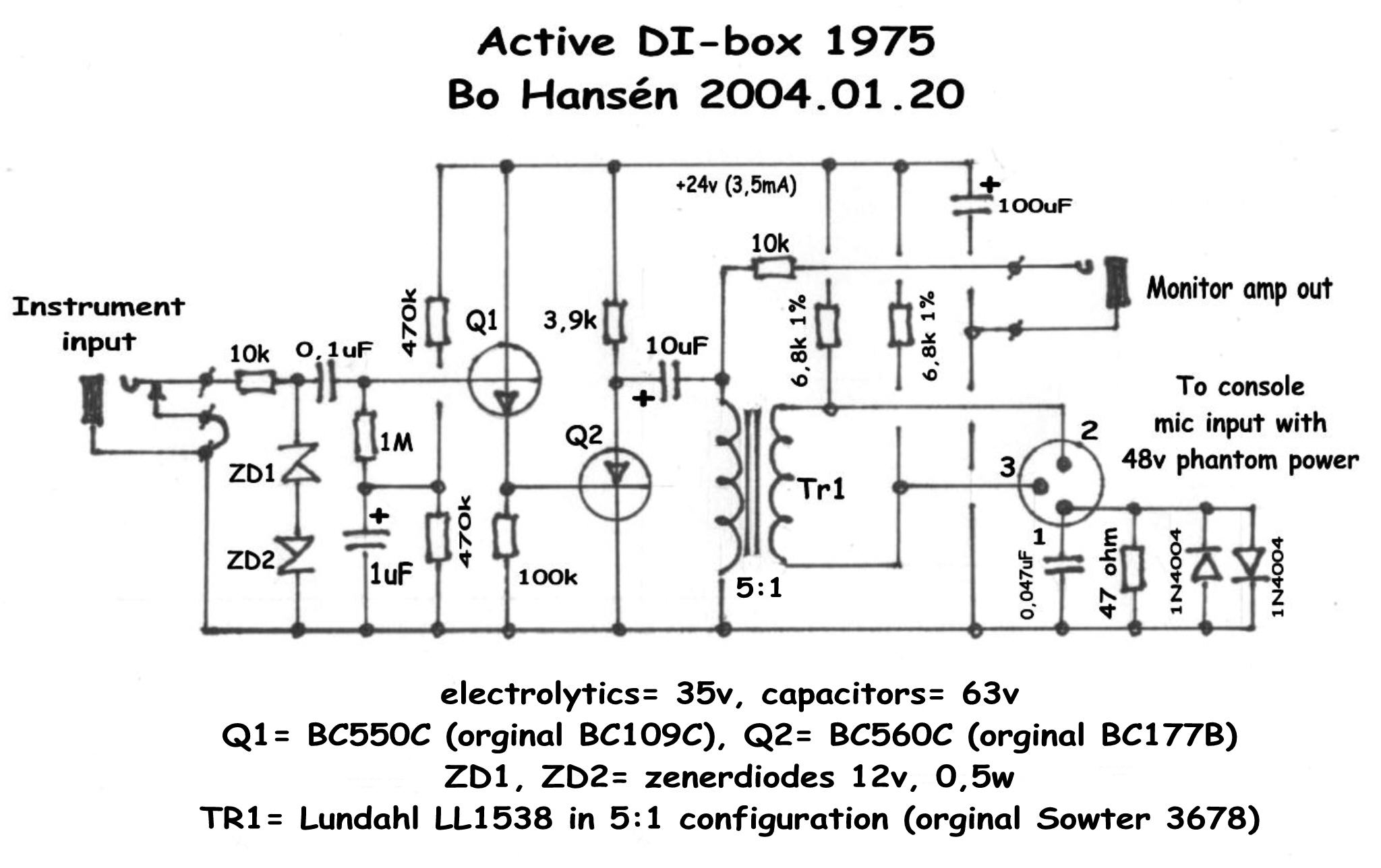
This is fine when both input and output are balanced.  Grounding based upon shields has the problem that the shields have long runs and can pick up lots of stuff, and if the output is converted to unbalanced at this point in the signal chain (TS cable, or unbalanced mixer) then all that noise becomes signal.  In that case the problem has been pretty well handled by Bo Hansen in the attached schematic where safety ground is via diodes but the chassis is isolated from the ground by a filter. Maybe (ricardo?) you would want to use Bo Hanson like ground approach to connect your star ground point to the chassis (if you were ever going to use unbalanced outs).  Check out bottom right corner, using this method you can ground/ground lift and still have a continuity above .7V of the incoming shield and outgoing ground.

Active%20DI%20box%201975.jpg


2) Ideally you don't want other paths to chassis.  Typically these would happen where the PSU and EDEN boards are mounted to the chassis, because they might ground the ground planes to the screw holes.  You can check this and use insulating standoffs if they are grounded.

 
bruce0 said:
1) There is an issue there though because the only ground on this chassis is through the shields of the equipment it connects to.
This is fine when both input and output are balanced.  Grounding based upon shields has the problem that the shields have long runs and can pick up lots of stuff, and if the output is converted to unbalanced at this point in the signal chain (TS cable, or unbalanced mixer) then all that noise becomes signal.  In that case the problem has been pretty well handled by Bo Hansen in the attached schematic where safety ground is via diodes but the chassis is isolated from the ground by a filter. Maybe (ricardo?) you would want to use Bo Hanson like ground approach to connect your star ground point to the chassis (if you were ever going to use unbalanced outs).

2) Ideally you don't want other paths to chassis.  Typically these would happen where the PSU and EDEN boards are mounted to the chassis, because they might ground the ground planes to the screw holes.  You can check this and use insulating standoffs if they are grounded.
I pontificate on this in #41.

In #56, each output TRS is isolated from Chassis and its Sleeve connected directly to its Eden.  To deal with RFI, the Sleeves are directly connected to Chassis via 100n Ceramics.
_______________

No unbalanced system is good for long lines.  If the TRS outputs are plugged into an unbal input, you will have problems.  You need to short Ring to Sleeve AT THE SOURCE.  ie at Eden.  This is a 'feature' of the TI & AD 'pseudo floating balanced outs'

There was stuff on http://www.proaudiodesignforum.com/ on this but it seems to have been removed.

Look up Self and Rod Elliot on this subject.
_______________

There's actually a 'Star Point' on Eden.  Its the junction between the 2 x 10u on the +/-15V.  But due to the EVIL ground plane, it's ambiguous and inaccessible  ;D

My #55 & #56 suggestions just try to make the best of it.
 
ricardo said:
outrecording said:
Thanks for noticing that. That ground needs to go somewhere.

And this portion of the schematic is for the Goldpoint attenuator I found on their website.
I didn't realise you were using a made up Volume Control Log Attenuator as your GAIN control.

If so, you have to wire it so the knob goes the wrong way .. ie CW decreases gain.  It needs to simulate a Reverse Log Pot.

The GND on the Goldpoint should NOT be connected.

I trust your recommendation, but I'm struggling to understand this. Would setting it up as a Audio Log bring some negative effects, as opposed to a Reverse Log?

For the wiring, looking at the Goldpoint schematic, I would need to bring my signal into the attenuator at that "GND" instead of the "IN", correct? Making position "1" full volume and "24" essentially off.
 
outrecording said:
I trust your recommendation, but I'm struggling to understand this. Would setting it up as a Audio Log bring some negative effects, as opposed to a Reverse Log?

For the wiring, looking at the Goldpoint schematic, I would need to bring my signal into the attenuator at that "GND" instead of the "IN", correct? Making position "1" full volume and "24" essentially off.
In a normal Log volume control, resistance changes in small steps near OFF (GND) and in big steps near MAX (IN)

A gain pot on this type of feedback amp, has maximum gain at small resistance so you have to make 2 connections.  One on the slider and the other on the end with small resistance steps.

If you do this with a normal Log volume control (like your Goldpoint attenuator) You'll find the knob goes the 'wrong' way .. CW is softer.  That's why people like Reverse Log Pots for this.  But it's only so the knob turns in the usual way .. CW is louder.

If you connect it up to the wrong end, you'll find hardly any gain change at all until near MAX when you'll suddenly have a huge gain change.

YES.  The 2 connections to your Goldpoint should be to Slider and to GND
 
That's what I thought you were getting at Ricardo, but didn't initially understand why it would behave like that. Going CCW is OK for me. Just need to adjust myself a bit.
 
bruce0 said:
As for R3 and R4, I think there the voltage drop is a big issue.  You are getting a load of 120ma, and across a 150R resistor that is too much drop (150 * .120 = 18V drop).  So you need a bigger cap and a lower value resistor.  But you can use low voltage caps which are smaller, so this should not present a size problem.  So for instance you could output 16V and engineer for a 1V drop 1/.120 = 8.3R... so use a 10 ohm resistor with 3300uF or LESS (because eden and other opamp based amps are good at common mode noise rejection they DON't NEED power to be as quiet).  There are several, they are not that big.  Here is a 3300uf search in mouser

You mention increasing the output by one volt. How can I do this without taking up a lot of space? This is where my lack of electronics knowledge is hurting me. (Google isn't yielding much for me.) There seems no way on the Murata itself to increase the voltage (unless I want 30V). Would doing this be as simple as adding a couple components after the Murata? Or would I need to look for a new DC converter outputting +/-16V?
 

Latest posts

Back
Top