Ahuja-Compensation

GroupDIY Audio Forum

Help Support GroupDIY Audio Forum:

This site may earn a commission from merchant affiliate links, including eBay, Amazon, and others.

Samuel Groner

Well-known member
Joined
Aug 19, 2004
Messages
2,940
Location
Zürich, Switzerland
Hi

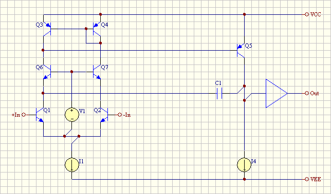
It is well known that the positive PSRR of a standard two-stage topology NPN input opamp is lacking perfection as frequency increases; amongst several possible fixes Ahuja presented an IEEE paper on cascoding the current junction (link for those with IEEE access).

Consider the following simplified schematic:
ahuja_compensation.gif

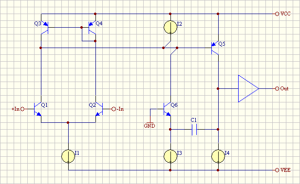
It is obvious that I2 needs to match the collector current of Q6 in order to avoid upsetting the input stage balance (which is not perfect to start with due to current mirror deficencies and Q5 base current, but let us ignore that at first). Anyone with a clever idea how this could be implemented for discrete amplifiers with little or no trimming need and low drift? Any references for bipolar IC opamps using that technique?

Samuel
 
I don't have strong opinions about such things, there's oddball devices you can make inside ICs that just don't translate to discrete, transistors with dual collectors and such. I find some of the newer high performance opamps kind of interesting, but doubt a discrete version would work as well without tight device matching and IC tricks.

Here is a link to a post about some variant on opamp design in another forum from a guy I find credible. While not exactly on topic he mentions PSRR in passing.

http://recforums.prosoundweb.com/index.php/m/315796/361/#msg_315796

JR
 
Bruno's post 315796 is a nice précis of a much-needed and possibly-nonexistent bigger article on opamps for audio. And it shows in some ways that we really don't need drastically different topologies for impeccable distortion performance.

I like his comment in his example of the cascoded stage: "Cascoding is also accepted by minimalists". :razz: He must be talking to some of the same people I am.

I hadn't seen the Ahuja scheme.

One general comment though: the current sources/sinks/limiters or whatever we want to call them, sprinkled throughout our designs, are taken tacitly, as a given. As we've seen with Jung's recent series and the reader followups, and in some of our discussions, they are a non-trivial part of design. There's a whole book devoted to them and voltage references that's not even close to exhaustive. There's more left to be said.
 
Thanks, I've seen Bruno's post--in fact it were his slides that pointed me to the IEEE paper. I think at least for discrete implementation there are much easier solutions to get PSRR up, but it's educationally worthwhile to study other approaches as well.

As we've seen with Jung's recent series.
BTW, did the promised third article ever got published?

Samuel
 
I think the series did get finished a while ago. No big surprises. In fact the more interesting things in some ways were the reader/WJ exchanges, which included the trick I discussed with you about improving PSR.

I was tempted to toss my comments in but didn't this time around.
 
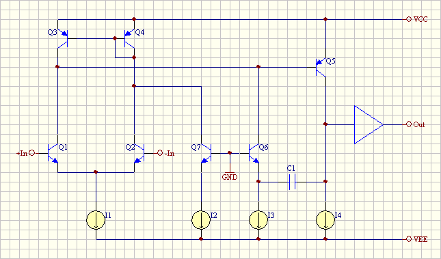
I had a quick e-mail conversation with Bruno Putzeys on the topic and he suggested an elegant solution which I can show with his permission:

ahuja_compensation_putzeys.gif


Q7 is my personal elaboration and reduces Q6 base current, thermal and early effect errors which might affect the match of I2 and I3. I2 and I3 are easy to match (almost) down to resistor mismatch even for a discrete implementation as they don't need to work at low voltages (allowing high bias voltage for the according transistors which renders Vbe mismatch neglible).

As shown it somewhat resembles a combination of a folded cascode and a standard two-stage topology. I think I've seen some roughly similar arrangements in IC precision opamps--need to dig in my archives...

Bruno asked me to add that the "possibly non-existent bigger article on op amps for audio" is one of those projects waiting for "when I have time". I hope to write it some day, I just don't know when.

As a further contribution to the discussion I'd like to add a closely related circuit as suggested by D. Self:

ahuja_compensation_self.gif


Self uses a cascode referenced to ground instead of the bootstrapped arrangement; the later seems preferable to me as it improves other parameters (mostly related to common mode effects) at the same time.

I'm not yet fully sure whether Ahuja's or Self's solution is generally speaking the better one; right now the second seems more appropriate as it does not affect input pair balance but improves the amplifier otherwise. Any input on this is appreciated.

Samuel
 
[quote author="Samuel Groner"]I had a quick e-mail conversation with Bruno Putzeys on the topic and he suggested an elegant solution which I can show with his permission:

ahuja_compensation_putzeys.gif


Q7 is my personal elaboration and reduces Q6 base current, thermal and early effect errors which might affect the match of I2 and I3. I2 and I3 are easy to match (almost) down to resistor mismatch even for a discrete implementation as they don't need to work at low voltages (allowing high bias voltage for the according transistors which renders Vbe mismatch neglible).
Samuel[/quote]

So Bruno had no Q7, just a direct connection from I2 to the I mirror input? It might be well to show the original for reference.

I like it (both) though. Note that for dynamical considerations the output impedance at Q6 collector will differ from Q7's. A small effect, but there might be some further optimization available by loading the emitter of Q7.

EDIT: the effect of loading at Q7 is tiny. However, once that, to begin with, you have equal impedances at the two inputs (my test case is 500 ohms to ground at +, a gain-of-two divider network at - ), then what really helps a lot is a little C to ground at the input of the I mirror.

For a 10V positive rail V the PSRR can be tweaked to 95dB and flat out past 200kHz. This is with perfect current sources, SA1015/SC1815 parts and an ideal unity-gain buffer, 100pF C1, and 1, 1, 1, 5 mA I sources from left to right.

EDIT 2: For a further enhancement of about 3dB, and now requiring almost no tweak C to ground at the mirror input, return base of Q7 to the emitter of Q6 instead of ground.

I suspect with a better current mirror like a Wilson, things could get better still, albeit with a reduction in rail swing and other complications.
 
So Bruno had no Q7, just a direct connection from I2 to the I mirror input? It might be well to show the original for reference.
He didn't show a schematic, just gave the hint.

For a further enhancement of about 3dB, and now requiring almost no tweak C to ground at the mirror input, return base of Q7 to the emitter of Q6 instead of ground.
That would be less ideal for DC precision, right? Why is there an AC advantage though?

Samuel
 
[quote author="Samuel Groner"]
So Bruno had no Q7, just a direct connection from I2 to the I mirror input? It might be well to show the original for reference.
He didn't show a schematic, just gave the hint.

For a further enhancement of about 3dB, and now requiring almost no tweak C to ground at the mirror input, return base of Q7 to the emitter of Q6 instead of ground.
That would be less ideal for DC precision, right? Why is there an AC advantage though?

Samuel[/quote]

Actually I believe may enhance d.c. PSR at least, if you look at the overall base current contributions. This is probably associated with the base current losses in the current mirror---which is what suggested it to me to begin with---the base current of Q7 is now subtracting from the emitter current of Q6.

I don't understand the AC behavior yet, but I went to a concert tonight instead of worrying about it :grin: Absolutely outstanding ensemble, Akademie für alte Musik Berlin. Calibrated my ears and reminded self of what we are doing this for.
 
Indeed I believe it was baroque tuning...

For more gushing about the band, if you can stand it, see the Rossi book thread in the Brewery.

Back on topic:

At these levels of attentuation and assumptions of identical parts, there's some question as to how realistic the real circuits would be. Parasitic C in layout will be important, certainly. When I did stick a Wilson mirror in, the low frequency rejection got still better, but there seemed to be no particular point of application for tweaking the high frequency performance, which was worse than achieved above with the simpler mirror.

Of course one hopes that the bypass caps and other decoupling components are taking care of high frequencies, so the performance at lower ones ought to be the focus.

At some point other approaches to PS rejection might be considered, like that cleanup circuit promoted on the guy's site that comes up when you google three-terminal regulator noise or something like those terms. It amounts to a two-pole lowpass with no d.c. connection of the active components to the line being filtered. I think it's been discussed in here once or twice.

EDIT: I'm confusing another thread with the one described. I'll try to find the two-pole cleanup one.

EDIT II: I'm now thinking the cleanup circuit is maybe not even the same as the two-pole approach I thought I recalled. More at 11...
 
http://www.wenzel.com/documents/finesse.html

This, on reacquaintance. is essentially a capacitance multiplier. The noise/ripple on an output line is cap-coupled to the input of a transconductance amp loaded with the series resistor, so that you get about unity inverting gain---hence cancel the coupled noise. The output response when optimized falls at 6dB per octave until the transconductance starts getting affected by a number of factors. A little C across the gm-setting R for the simple transistor stage can help a lot.

You can also keep the rolloff at higher frequencies going by an additional output capacitor downstream from the resistor. Most of the other parts are just there to bias the transconductance amp, and this gets tricky when gm gets large and Rseries small. The author candidly admits that at some point a low-noise voltage regulator may be a simpler solution.

The two-pole filter is another matter, something I did a little development of after seeing the above material. It's not ready for prime time yet.
 
[quote author="bcarso"]http://www.wenzel.com/documents/finesse.html

This, on reacquaintance. is essentially a capacitance multiplier. The noise/ripple on an output line is cap-coupled to the input of a transconductance amp loaded with the series resistor, so that you get about unity inverting gain---hence cancel the coupled noise. The output response when optimized falls at 6dB per octave until the transconductance starts getting affected by a number of factors. A little C across the gm-setting R for the simple transistor stage can help a lot.

You can also keep the rolloff at higher frequencies going by an additional output capacitor downstream from the resistor. Most of the other parts are just there to bias the transconductance amp, and this gets tricky when gm gets large and Rseries small. The author candidly admits that at some point a low-noise voltage regulator may be a simpler solution.

The two-pole filter is another matter, something I did a little development of after seeing the above material. It's not ready for prime time yet.[/quote]

That seems a long way to go to get a lower noise VR. I rolled my own from a TL072 and a couple bipolar transistors when I wanted better than a 3 terminal for a phono pre.

JR
 
Some simulation results comparing standard (green), Ahuja (red) and the Self (blue) compensation approach:

ahuja_psrr.gif
ahuja_gain.gif

I used a standard amplifier with darlington VAS and simple emitter follower output. Current and voltage sources were still ideal, but this shouldn't have a significant effect for these considerations.

With respect to PSRR, both enhanced approaches seem to be more or less equivalent for practical reasons. Gain-wise Ahuja seems even to shift the secondary poles upwards while the Self method is relatively ill-defined in the 100 MHz region. This seems to be some sort of interaction with the CMRR of the amplifier as grounding the cascode clearly improved the situation.

Samuel
 

Latest posts

Back
Top