[BUILD] 1176LN Rev D DIY

GroupDIY Audio Forum

Help Support GroupDIY Audio Forum:

This site may earn a commission from merchant affiliate links, including eBay, Amazon, and others.
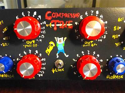
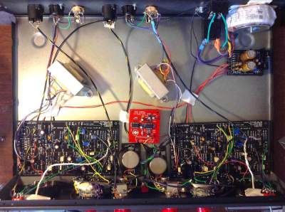
I've got mine all finished and boxed up. It's a stereo pair. Had a few problems along the way but it's sorted out now.

compressor-time-dual-1176.jpg

compressor-time-panel-detail.jpg
compressor-time-inside.jpg


Sounds amazing, and the stereo linking boards work perfectly. I made a few extra mods:

1) Added several ratios -- all between 2:1 and 10:1, plus "?!," which jumpers the threshold setting of 20:1 and the CV setting of 2:1. The end result is an insane level of crushing but without the all buttons in distortion (which I didn't particularly care for). The rotaries are nice heavy duty 12-position ones but they made the method of securing the ratio boards a little embarrassing looking (it's heavy duty double sided tape ... the boards aren't going anywhere but it does look cheesy).

2) Bypass is on the volume knob as a push-pull.

3) Attack goes up to 8mS.

4) Dropped +8 mode from the meters.

We've been watching a lot of Adventure Time, so Jake and Finn went on this.

----

I have what MAY be a meter issue in the right channel, though. If I do the first two calibration steps, when I have 0V across R74, when I go back into the "Normal" jumper, the meter drops to -20, and R71 is insufficient to make it budge. If I measure the DC volts on Q13's base in that circumstance, it's a good half volt above where it should be. The left channel is correct. If I ignore the warning not to touch R75 again and just set the base on Q13 to what the schematic says its voltage should be, I can do calibration step 3 just fine. The collector voltages end up where they're supposed to be, too, and they pretty much match the other unit. The only thing I can detect might be off is that I think the meter in the right channel reacts a little harder than the left. Not by much, maybe a dB or two on the higher ratios (using a kick drum pulse to check). The FETs and meter BJTs in both channels are matched quads. I've pulled and measured every resistor in the meter section, and everything else works as advertised. Should I just not worry about it? EDIT: I've decided to chalk this up to tolerances in discrete components and the meters. If I wanted perfection in the meter driver I guess I should have built a Revision G. I have digital metering on the other end of things anyway :)
 
I finally got around to building my mnats 1176 (in a dual hairball case). It passes signal.

However, I can't seem to get the "Q bias adjustment" working. I have the input/output levels set so that the meter reads +1. When I adjust the 'Q' trimmer from end to (about 0 ... -3v on the wiper) it has no effect at all on the meter (stays exactly +1).  What should I check first?
 
Hi all ,

My once beautifully working mnats rev D has decided to start misbehaving.

Today in a session it stopped compressing / no gain reduction. With the meter in GR mode, the needle doesn't move, it isn't responsive to any change in the controls. 

I cracked open the lid, checked for any faulty wiring etc.
I then measured all the transistor voltages against the schematic on mnats site - they are all correct.

I decided to complete the calibration steps again and in the meter tracking step I don't get the expected -10db drop when engaging GR on the attack switch. In fact I don't get a drop at all.

Having looked over all the wiring and checked voltages I'm running out of thoughts as to what next.

Could the attack switch be the culprit? Even though I have gone over it.

Appreciate any insight !
 
frazzman:

I assume it's passing signal, just not compressing.

To eliminate the attack switch as the culprit: Put your multimeter in continuity (beep) mode and verify that it connects when you turn the switch.

If the switch is working, this is what I would do:

If all your transistor voltages are correct, you can measure DC on the gate of the FETs with and without signal present and observe if DC is making it to the gates of the FETs. It will swing to a negative voltage (from the rectifier) when signal is present. You will also be able to measure a resistance drop from the drain to source of the FETs. And the behavior should be roughly the same between both FETs.

If you are NOT getting DC at the FETs, trace the signal in the schematic backwards to the attack pot and decay pot and then back to the rectifier diodes and see if you have DC at the rectifier. If you have DC there but none at the FETs, your problem exists somewhere between those two points. If you are getting DC there, then you can probe for signal while running a test tone (an audio probe or AC through a large capacitor connected to your multimeter's probe) starting at the volume control and following through the ratio switching to the input of the side chain, and follow through until you lose signal. If/when you find that there is no audio present, you can start examining the components in that area.

If you ARE getting DC at the gate of the FETs but you AREN'T getting a resistance change, then first reflow the solder joints on the FETs. (Also, if they're in a socket, carefully solder them to the socket ... the socket might be loose and they could be failing to make good contact.) If that doesn't work, then you might need to replace the FET, though I'm at a loss to guess what could kill a FET like that.
 
midwayfair said:
frazzman:

I assume it's passing signal, just not compressing.

To eliminate the attack switch as the culprit: Put your multimeter in continuity (beep) mode and verify that it connects when you turn the switch.

If the switch is working, this is what I would do:

If all your transistor voltages are correct, you can measure DC on the gate of the FETs with and without signal present and observe if DC is making it to the gates of the FETs. It will swing to a negative voltage (from the rectifier) when signal is present. You will also be able to measure a resistance drop from the drain to source of the FETs. And the behavior should be roughly the same between both FETs.

If you are NOT getting DC at the FETs, trace the signal in the schematic backwards to the attack pot and decay pot and then back to the rectifier diodes and see if you have DC at the rectifier. If you have DC there but none at the FETs, your problem exists somewhere between those two points. If you are getting DC there, then you can probe for signal while running a test tone (an audio probe or AC through a large capacitor connected to your multimeter's probe) starting at the volume control and following through the ratio switching to the input of the side chain, and follow through until you lose signal. If/when you find that there is no audio present, you can start examining the components in that area.

If you ARE getting DC at the gate of the FETs but you AREN'T getting a resistance change, then first reflow the solder joints on the FETs. (Also, if they're in a socket, carefully solder them to the socket ... the socket might be loose and they could be failing to make good contact.) If that doesn't work, then you might need to replace the FET, though I'm at a loss to guess what could kill a FET like that.

Thanks for your reply and help!

Yes - I am passing signal just fine but no compression. As I mentioned, this unit was working perfectly well until a few days ago where this problem suddenly emerged.

The attack pot SPDT checks out ok, I can measure continuity on each throw as the switch is toggled.

With regards to the DC readings on the FETs, I can measure DC on the gate of both which is around -1vdc but it doesn't seem to differ between signal present or no signal. Infact, it doesn't really seem to vary at all. DC readings on the drains are in line with the measurements on the mnats schematic.

With regards to the resistive change between source and drain, I'm not entirely sure I follow. Are you saying this should vary with signal ? I can measure resistance here but I'm not sure I'm interpreting the result properly.

The FETs are both soldered directly to the mainboard, only the other transistors are socketed. I've reseated them all but I guess I couldn't rule out a dodgy connection there ...

EDIT: just did a quick measurement ... 1khz sine wave input - I'm getting no AC on pad 22, irrespective of what ratio I'm selecting. This must be my problem.

Pad 21 - DC measures ok - voltage changes as you change ratio - it gets more negative as ratio gets higher

Pad 19 - DC voltage changes as the release pot is turned

 
You can use the continuity setting on your multimeter to make sure that the volume pot is actually connected to the side chain components through all the switches. I should remember what all the pad numbers are because I had to trace them for my build, but I've already forgotten ... :p
 
midwayfair said:
You can use the continuity setting on your multimeter to make sure that the volume pot is actually connected to the side chain components through all the switches. I should remember what all the pad numbers are because I had to trace them for my build, but I've already forgotten ... :p

I just rechecked my measurements and it looks like pad 19 and 21 are correct. I updated my previous post to reflect that.

So it's just pad 22 that looks odd to me, how can I not have any AC there?
The switch is working correctly, it is switching "GRN" to pad 22 as it should.

When you say volume, do you mean output pot ? How does that come into play here ?
 
frazzman said:
When you say volume, do you mean output pot ? How does that come into play here ?

Yeah, the output pot.

Someone else will have to jump in on the pad 22 question. I'm not exactly sure which components that is supposed to connect to. But I can give you the locations to follow/test until you lose signal.

The sidechain is connected to the audio path from lug 3 of the output pot, through a chain of resistors, each of which shorts (at different ratio settings) to a large (1uF, C17) capacitor at the input of the side chain.

The switch on the back of the attack pot switches the side chain's input capacitor between ground* and the lugs on the switch that short to different spots along that chain of resistors.

*this ensures that there's no noise to be amplified by the sidechain that would be rectified and eventually appear as negative DC at the FET gates, which would cause gain reduction even when the bypass is flipped.

Note that if you have a little bench amp and you aren't sure if something's wrong with the multimeter measurement (I don't know if mine works the same way as yours), you can just use a mono cable plugged into an amp, ground its sleeve to the compressor's star ground, and attach a capacitor to its tip with an aligator clip. When you touch the other side of the capacitor to a spot that should have some audio, you should get a signal on the amp. (Or you can mute software playback from your DAW and plug the cable into your interface instead of a small amp, whatever's most convenient.)

The spots exact spots to follow the signal would be:
R23 lug 3 -- you must have signal here, because you are getting signal at the output.
R78 -- one side of this is connected to R23; the other side is connected to ratio 20:1. Check that you have signal on both sides of the resistor, and, for the side connected to ratio 20:1, that you have signal on the switch only when the switch is pressed.
R19: this is the 12:1 resistor, same procedure.
R20: 8:1, same procedure
r21: 4:1, ditto.
R22: One side is grounded at all times; you should have signal on the other side of it. The signal will be fairly weak there, since it's a 226K/47K voltage divider at that point, but it should be there.

If at any stage along this chain you find that you don't have signal, you need to check the wiring for continuity, and ensure that something goofy didn't happen like your signal getting shorted to ground.

Next probe at the common lug of the GR on/off switch. If you had signal on all ratio lugs, you will have signal at this point only when the GR is ON. This lug should be grounded when it's off. (Which you can check with continuity.) If you don't have signal when it's "on," then same thing as before: Check your wires and make sure that you have full continuity to the ratio switches and that your signal is not shorting to ground somehow.

The next step is to verify that your signal makes it from the common lug of the switch to the negative side of C17. If it doesn't, locate the wire, do your continuity checks, and then continue. It's a major pain to get to this since the only place to put a probe is under the PCB, but one of the wires from the ratio PCB connects there. I just can't remember which one.

You should have your normal signal at the collector of Q7, the base and emitter of Q8, all three pins of Q9, and base and emitter of Q10. Keep following. Once you hit the diodes, it'll change from a nice 1K sine wave to something distorted sounding (that's your rectified signal) and you can probably just switch to DC measurements.
 
midwayfair said:
frazzman said:
When you say volume, do you mean output pot ? How does that come into play here ?

Yeah, the output pot.

Someone else will have to jump in on the pad 22 question. I'm not exactly sure which components that is supposed to connect to. But I can give you the locations to follow/test until you lose signal.

The sidechain is connected to the audio path from lug 3 of the output pot, through a chain of resistors, each of which shorts (at different ratio settings) to a large (1uF, C17) capacitor at the input of the side chain.

The switch on the back of the attack pot switches the side chain's input capacitor between ground* and the lugs on the switch that short to different spots along that chain of resistors.

*this ensures that there's no noise to be amplified by the sidechain that would be rectified and eventually appear as negative DC at the FET gates, which would cause gain reduction even when the bypass is flipped.

Note that if you have a little bench amp and you aren't sure if something's wrong with the multimeter measurement (I don't know if mine works the same way as yours), you can just use a mono cable plugged into an amp, ground its sleeve to the compressor's star ground, and attach a capacitor to its tip with an aligator clip. When you touch the other side of the capacitor to a spot that should have some audio, you should get a signal on the amp. (Or you can mute software playback from your DAW and plug the cable into your interface instead of a small amp, whatever's most convenient.)

The spots exact spots to follow the signal would be:
R23 lug 3 -- you must have signal here, because you are getting signal at the output.
R78 -- one side of this is connected to R23; the other side is connected to ratio 20:1. Check that you have signal on both sides of the resistor, and, for the side connected to ratio 20:1, that you have signal on the switch only when the switch is pressed.
R19: this is the 12:1 resistor, same procedure.
R20: 8:1, same procedure
r21: 4:1, ditto.
R22: One side is grounded at all times; you should have signal on the other side of it. The signal will be fairly weak there, since it's a 226K/47K voltage divider at that point, but it should be there.

If at any stage along this chain you find that you don't have signal, you need to check the wiring for continuity, and ensure that something goofy didn't happen like your signal getting shorted to ground.

Next probe at the common lug of the GR on/off switch. If you had signal on all ratio lugs, you will have signal at this point only when the GR is ON. This lug should be grounded when it's off. (Which you can check with continuity.) If you don't have signal when it's "on," then same thing as before: Check your wires and make sure that you have full continuity to the ratio switches and that your signal is not shorting to ground somehow.

The next step is to verify that your signal makes it from the common lug of the switch to the negative side of C17. If it doesn't, locate the wire, do your continuity checks, and then continue. It's a major pain to get to this since the only place to put a probe is under the PCB, but one of the wires from the ratio PCB connects there. I just can't remember which one.

You should have your normal signal at the collector of Q7, the base and emitter of Q8, all three pins of Q9, and base and emitter of Q10. Keep following. Once you hit the diodes, it'll change from a nice 1K sine wave to something distorted sounding (that's your rectified signal) and you can probably just switch to DC measurements.

Midwayfair, thank you so much for that detailed and concise explanation, I really appreciate the time it would have taken to put that reply together.

And I'm pleased to say that your steps helped me find the trouble spot. A cold solder joint on the ratio board. Once I dug my scope out and started following through it became pretty clear where the problem was.

We are back up and running again. 

Pad 22 is the sidechain input but you were already on the ball with that when you mentioned C17.

Anyway, thanks again. Much good DIY karma to you sir.
 
Hi Guys,
My Rev D (mnats board, hairball kit), has a strange issue. After successful calibration, when I put the meter in GR mode, the needle will drift up and down very slowly.

It'll hover around 0dB, but will slowly move up to -1, and down to +1dB, sometimes more. It's a slow movement ex: will take a couple of minutes to move. It repeats the movements and won't stabilize with time.

Audio and compression sound good. Any ideas on what to check?

Thanks!

 
dalmaproductions said:
Hi Guys,
My Rev D (mnats board, hairball kit), has a strange issue. After successful calibration, when I put the meter in GR mode, the needle will drift up and down very slowly.

It'll hover around 0dB, but will slowly move up to -1, and down to +1dB, sometimes more. It's a slow movement ex: will take a couple of minutes to move. It repeats the movements and won't stabilize with time.

Audio and compression sound good. Any ideas on what to check?

Thanks!

Check the FAQ linked from the first post of this thread. I think that issue is specifically mentioned there...
 
Hey guys, quick question.

I'm building myself the 2.2 version mnats and was going through the B.O.M list. Noticed on capacitors like c7, c10, and c17 you can either choose film or electrolytic of 1uF. If i choose electrolytic, is there a certain voltage value of capacitors I have to choose or can it be whichever electrolytic with the 1uF?

Thanks!
 
ln76d said:
You can use 35V rated without any problem. Personally i would use film caps in these positions.

Nice thanks for clearing that up!


Btw another quick question, as a newbie in electronics is it better to purchase the Hairball 1176 kit or DIY with BOM of Mnats?

How much difference in difficulty do both offer?
 
All depends on your location. If you live in US, probably due to many shipments hairball kit would be cheaper.
If you live outside and have to pay all taxes, fees and other thievery, then it can be more profitable to source parts from few suppliers.
For example i bought from Hairball front Panel, knobs, switches, attenuator and boards for Rev F.
Most of caps and resistors i already had, ordered custom power transformer, bought UTC O-12 on ebay (in my opinion worth to look for - this is really important part of sound of original UA/UREI compressors), I had original output tranny, had no problem to find VU meter for cheap etc.
Usual original types of  transistors  are hard to source - still depends on location.
For passive components i have my own preferences, so i usual don't like these type of  kits.
 
ln76d said:
All depends on your location. If you live in US, probably due to many shipments hairball kit would be cheaper.
If you live outside and have to pay all taxes, fees and other thievery, then it can be more profitable to source parts from few suppliers.
For example i bought from Hairball front Panel, knobs, switches, attenuator and boards for Rev F.
Most of caps and resistors i already had, ordered custom power transformer, bought UTC O-12 on ebay (in my opinion worth to look for - this is really important part of sound of original UA/UREI compressors), I had original output tranny, had no problem to find VU meter for cheap etc.
Usual original types of  transistors  are hard to source - still depends on location.
For passive components i have my own preferences, so i usual don't like these type of  kits.

In that case it would be better for me to purchase the parts individually since I live in Europe.


Though I have an unrelated question if you wouldn't mind answering.

The Mnats BOM, I suppose, is based on the ratio/meter rotary function correct?
If I wanted to use the Push Button functions, then I would also have to purchase the separate Ratio & Meter board  from Hairball Audio?
And also, is there a pcb diagram or BOM list for the meter and ratio PCB from Hairball I could check?
I saw a picture of the ratio PCB from Hairball which had on it R1,R2,R3 resistors but couldn't find anything about those resistors in the Mnats 1176 BOM.

It might not be something to worry about, but seeing as I am trying to learn more I want to avoid to miss something before purchasing the parts.

EDIT:
FOUND HAIRBALL RATIO PCB VALUES NO NEED TO ANSWER THAT ANYMORE
 

Latest posts

Back
Top