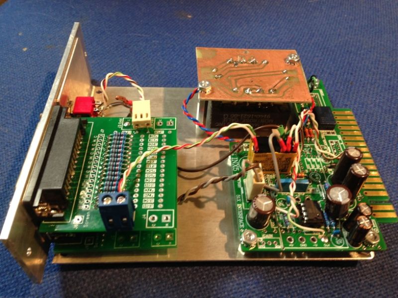
DB25 summing PCB - MK2??

GroupDIY Audio Forum

Help Support GroupDIY Audio Forum:

This site may earn a commission from merchant affiliate links, including eBay, Amazon, and others.
As Brian rightly says, if you insert a series resistor its no longer a virtual earth. What you really need is a 4PDT toggle switch (they do exist). Connect on pair of wipers to the DB25 PCB bus outputs. Connect the other pair of wipers to your hot and cold output connector. In one position you wire the switch so the input goes to the VE amp and the amp output goes to the output connector. The other position you wire so it acts like a bypass with the slugging resistors attached.

I wish there was a quick way we could draw little free hand sketches directly in a post - Ethan??

Cheers

Ian

P.S. oops, the right hand switch is shown in the wrong position.
 

Attachments

  • vebypass.png
    vebypass.png
    30.5 KB · Views: 75
Brian. Ian, of course you are right - the series resistor would not be virtual earth and would allow channel cross talk and screw with the gain structure as I add and remove channels to sum... so that is out.

I have already got a switch activating a relay, I think I can use the same power  to power a second relay to disconnect the front half (although the mounting might get a bit messy) and potentially noisy (bang) when switched.

I will try it now.
 
Ok, this works.  I "dead bug" mounted a 24V relay to the board and switched the balanced bus to the Virtual Earth or directly to the output pins.

This is not really "bypass" although the 500 series pins for input and output are connected together.  Connecting the input to the output of another summing module would actually allow summing of more channels in passive mode.  In active mode the input is disconnected. 

What happens is:

In passive mode the input is connected to the output and to the output of the summing bus and a shunt is dropped into place across the bus (I used 249R resistor).  The both output pins and input pins is the balanced summing bus. 

In active mode the input is unconnected.  The Output is connected to the transformer secondary.  The shunt is removed from the summing bus.  The Hot summing bus and cold summing bus are each connected to a virtual ground amp that each drive one end of the transformer primary.  The transformer polarity is reversed to correct the inversion of the opamps.  Since ground noise in both Hot and Cold bus is amplified on both ends of the primary it should cancel out.

In both active and passive modes the summed grounds are all tied together and to the chassis and DB25 shell and the 500 Series audio ground (pin 5) is optionally open via an INX5 gnd/lift strap.

null_zps44c11679.jpg


Each summed channel lowers the impedance of the bus, so the Virtual Earth amp gain changes to keep the output level sort in a reasonable range, and that seems to work.

Not really sure how that works on the bus that is summed and output with a shunt to a mic preamp but I imagine that the more summed channels the higher the level running into the combining amp (anyone have experience with that?  What do I do just pad it when the level gets too high?)

Also if I plug in even a single example of an unbalanced channel in it basically grounds out the cold bus.  I suspect this would have the following result:  1) the ground noise cancellation approach would no longer work, and ground noise would go up by 6db? 2) Any electronically balanced inputs would have lower output levels or other effects depending upon design.  3) If it was unbalanced with a trs cabling it could have some pretty large ground noise pickup capability.

Does that sound right?

I will build a second and do some summing.
 
And it sounds good, very quiet in both modes.

But I have a problem, the opamp gets really hot and clips at low levels (around 1v RMS).  I think that is happening because it is only outputting the difference between the positive and negative sum, but the opamps are amplifying signals that are larger than the difference (because both legs are floating relative to ground), and I don't know how to deal with that. 

any ideas?

Works great with the power off or in passive mode.

 
The first thing to do is establish the gain in VE mode. Feed a signal of known level into just one input and measure the output level. It should be the same.

The other thing to do is to try it with the transformer disconnected.

Cheers

Ian
 
Ian:

Good ideas. 

I did check the gain.  The output level is pretty independent of the number of channels for pink noise inputs.  Two inverted inputs cancel (obviously) sine wave inputs double if they are in phase.

I have not checked to see if the gain is exactly 1 for a single input, I will do that.

I hadn't thought of disconnecting the trafo, but that is a good idea too... the configuration should work fine (but inverted).  Will try it and post back.

(By the way Ian ... thanks are in order these are GREAT little boards, very simply and nicely designed with all the pads I need to do whatever I want.  In fact I think the let me do a bit too much (I now have a VU meter on the output!)).
 
ok, The gain is higher than I expected (2) because each opamp amplifies at unity, and thus the output is 2 oposite unities, or 2.  So the gain is 2.

I am not sure I can make the gain 1, because that would require the gain to be .5 on the opamps, no?

The gain on a single channel is 2, on larger number of channels it reduces, as the input impedance decreases with more parallel channels.


I did disconnect the transformer and got the above numbers, and the opamp case gets a LOT less hot.  So I don't really know what that means I guess it can't drive the transformer.

Any ideas what to do now?  If I put in higher resistors between the opamp output and the transformer wouldn't I get a frequency response problem ? 

I could wire the trafo as a step down (3:1 step down is easy with this trafo).  That would lower the DCR of the primary and probably lower the loading and bring the gain under 1...

I am a little lost on this but I really want to keep a transformer on the active mode because without it an unbalanced connection on output shorts out one of the opamps and that seems ... well bad...
 
Ok wired as 3:1 step down it seems ok. No hotter than transformerless

Noise seems fine , sounds fine, will measure thd and noise later

Any reason I should aim for exactly unity gain on this? Right now a .77 vRMS Sine wave outputs about .5V RMS is ( gain of .66 )
 
There's no reason to go for unity gain. If you have several sources being summed the output will tend to rise anyway. As long as you know what it is, that's all that matters.

Cheers

Ian
 
Ok, thanks! I will leave the gain less than unity, it is about .66, at least for now.

The way the virtual earth amp works as I add sources the input impedance goes down (each source parallels another 6.2K resistor) and that decreases the gain somewhat, so it tends to stay "unity", although with the .66 gain and the step down and the two amps doing sort of push pull I have to say I am not sure how it will work.  I will report back.
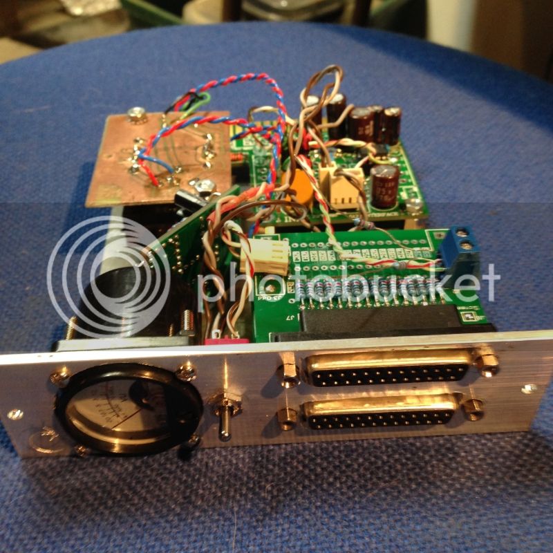
For the moment I am tired of grinding DB25 slots so I broke down and ordered a couple of front panel express panels.  I put a "vu" meter on it as well, with little JLM driver cards (no room for my Peak reading card).

 
bruce0 said:
Ok, thanks! I will leave the gain less than unity, it is about .66, at least for now.

The way the virtual earth amp works as I add sources the input impedance goes down (each source parallels another 6.2K resistor) and that decreases the gain somewhat, so it tends to stay "unity", although with the .66 gain and the step down and the two amps doing sort of push pull I have to say I am not sure how it will work.  I will report back.

Have you tried adding sources and measuring the output because if it is a true virtual earth the gain for each and every input should be the same no matter how many inputs are used. So if you connect the same signal to two inputs the output should double. In other words the gain should not decrease.

Cheers

Ian
 
Ian, you are far better at this than I am.  So please correct me if I am wrong but:

an inverting opamp gain is -Feedback R/Input R

Feedback R is fixed

Input R is the parallel combination of all the "plugged in" input channels (in my configuration which is balanced this is the parallel combination of all of the "Hot" sides to ground on one amp and all of the "cold" sides to ground on the other amp. These two amps are then output ... Hot as cold, and Cold as Hot through an output transformer in order to re-invert the signal (I think/hope cancel any ground noise). )

Unplugged channels are open to ground.

My summing resistors at 6.2K and 1 to 16 channels means that my Input R is between 6.2K and 387R.

Since the output impedance of the various summed inputs can be approximated as 0 ohms, and they are combined with 6.2K ohm resistors, then the Input R for 1 channel is 6.2K for 2 channels is 3.1K, for 4 channels is 1.55 etc.  I used a 12.4K Feedback R So the gain of the amp for 1 channel is -2, for 2 channels is -1, for 4 channels is -.5 and so on.

This is all briefly (and better) described in the Forsell summing article, although I think the ground noise cancellation approach he suggests may be different from my approach.  He describes a 6dB improvement for ground noise in a balanced environment, but I believe this would cancel much more ground noise than that depending upon amp precision and transformer response.  I am way out of my league on that matter though.

So the result is...
If the signals are "coherent" then the output stays near the average input.  Two identical input sine waves are a good example of that.

If the signals are "incoherent" then there is some cancellation and the output falls a bit from the average. (two out of phase sine waves cancel as  an extreme example.  Different noise signals together cancel partially).

I may have it wrong.  But it seems to be working just about like I describe.


I think a non-inverting summing amp (like my box in passive mode) does about what you describe, the more coherent channels, the more output signal and less gain needed.  There is some crosstalk between channels in that approach as well I think.  I have less experience in this mode though.

 
Ian... Mea-half-a-culpa.... my measurements seem to bear out what you are saying some of the time.  here is the data that I find confusing:

Initial conditions:  I rewired the amp with a gain of 1, and 1:1 transformer

I put a single 4dBu (1.24V RMS) sine wave in and get the same level out.
I sum two 4dBu sine waves in and get 2.48V RMS (10dBu)

So that seems to work like you are saying... but the following is confusing:

If I put a -20dBu pink noise signal in, I get -20dB out.
If I put two -20dBu pink noise signals in, I get -20dB out.

And that seems to work like I am saying.

So ... I am befuddled.  Any idea about why?

I am only building one of these till the faceplates arrive.  They are a bear to cut.
null_zpsfe2aeff5.jpg
 
Thanks for the latin lesson! 8)  I will put up more pictures when the new panels come in and I finish the pair.  I need to try them out, they work but I have a bunch of questions about how I wired them them which I put up on JLM audio board.
 
bruce0 said:
Ian... Mea-half-a-culpa.... my measurements seem to bear out what you are saying some of the time.  here is the data that I find confusing:

Initial conditions:  I rewired the amp with a gain of 1, and 1:1 transformer

I put a single 4dBu (1.24V RMS) sine wave in and get the same level out.
I sum two 4dBu sine waves in and get 2.48V RMS (10dBu)

So that seems to work like you are saying... but the following is confusing:

If I put a -20dBu pink noise signal in, I get -20dB out.
If I put two -20dBu pink noise signals in, I get -20dB out.

And that seems to work like I am saying.

So ... I am befuddled.  Any idea about why?

It is probably a combination of things. First it is to do with the correlation between the two signals - correlation is just a fancy word that means how similar two things are. Two identical sine waves have 100% correlation because they are ..er identical so the output of the summer should be a signal twice as big i.e 6dB greater.

Genuine  independent random noise signals should be completely uncorrelated so the will not be 6dB greater when added together. I won't bore you with the maths but basically their powers add rather than their amplitudes which means their sum should be 3dB greater.

The strange thing is your two pink noise sources don't seem to add at all. This could possibly be because they are not entirely independent or it may be something to do with the response of the meter you are using.

Audio signals are somewhere in between noise and 100% correlated signals. As different sources tend to occupy different frequency bands, a good approximation is to assume they add like noise i.e two signals will be 3dB bigger than one on its own. This is why I said in an earlier post that as you add more channels the output will tend to go up.

Cheers

Ian
 
Well my pink noise measurements are not as exact because the level is low and my oscilloscope based measurements of the same signals are tough because they jump around a bit... 

I understand the correlation thing.

And two 100% uncorrelated signals (two sine signals, one inverted) I have tried and they output null signal.
 
Back
Top