You are using an out of date browser. It may not display this or other websites correctly.
You should upgrade or use an alternative browser.
You should upgrade or use an alternative browser.
DB25 summing PCB - MK2??
- Thread starter ruffrecords
- Start date


Help Support GroupDIY Audio Forum:
This site may earn a commission from merchant affiliate
links, including eBay, Amazon, and others.

Sorry...
You are correct they are not used.
Further, everything in the red boxes on the schematic is not used.
One outstanding question (which nobody has answered) is do I need some sort of "grid resistor" on this thing. That resistor would if it was needed attach where R17 and R14 are and go to ground, but I don't have that now... I just wonder if it is needed.
If you are doing one of these, I have a fpd file for a front panel, I ordered a couple.
ruffrecords
Well-known member
bruce0 said:One outstanding question (which nobody has answered) is do I need some sort of "grid resistor" on this thing. That resistor would if it was needed attach where R17 and R14 are and go to ground, but I don't have that now... I just wonder if it is needed.
No, you don't need any. The -ve inputs of the op amps gets their dc bias via the feedback resistors R16 and R18.
Cheers
Ian
moreover, with r17 the IC2b offset voltage is 2x than without it, to be precise, but this is not a problem in any case.
But the real problem is that ic2b keeps the signal from ic2a's out by R17 so the CMRR becames a disaster.
But the real problem is that ic2b keeps the signal from ic2a's out by R17 so the CMRR becames a disaster.
ppa said:But the real problem is that ic2b keeps the signal from ic2a's out by R17 so the CMRR becames a disaster.
PPA - yes - you are correct that would be bad. Under no circumstances should R17 be installed as in the original schematic to connect the two opamp halves. As Ian said ( and thank you Ian I finally understand) the feedback resistors provide the dc bias.
Front Panel Express file - ordered but not yet verified since I won't get them till mid month.
I will post pictures when I get them and try them for fit.
Note: on the DB25 connectors, for the jack screws I drilled a big hole on top of a small hole to deal with the thickness of the front panel (you can see I did this by hand in my prototype panel) and don't know how that will work out with front panel express - will let you know.
Site doesn't allow .fpd files so I changed the extension to .txt and you should change it back to .fpd so it will open
(Updated 10/8/2013 - version 4 of front panel still not verified but removed threaded holes for VU meter and replaced them with clearance holes.
Attachments
bruce0 said:Front Panel Express file - ordered but not yet verified since I won't get them till mid month.
I will post pictures when I get them and try them for fit.
Note: on the DB25 connectors, for the jack screws I drilled a big hole on top of a small hole to deal with the thickness of the front panel (you can see I did this by hand in my prototype panel) and don't know how that will work out with front panel express - will let you know.
Site doesn't allow .fpd files so I changed the extension to .txt and you should change it back to .fpd so it will open
many thanks
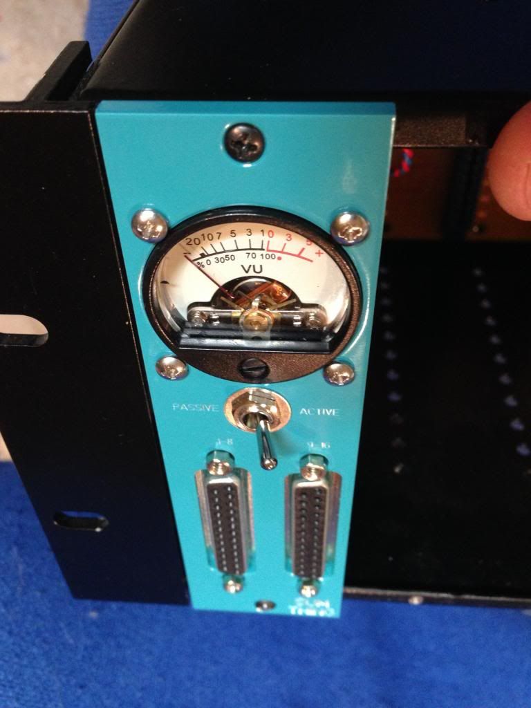
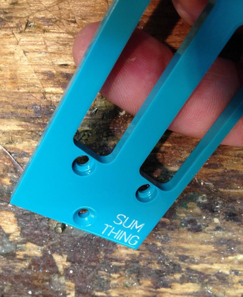
There are problems with the front panel express file. I received the panels and I made another mistake which was I selected a color but removed the "infill color" checkbox. You can see it is just bare aluminum engraving.
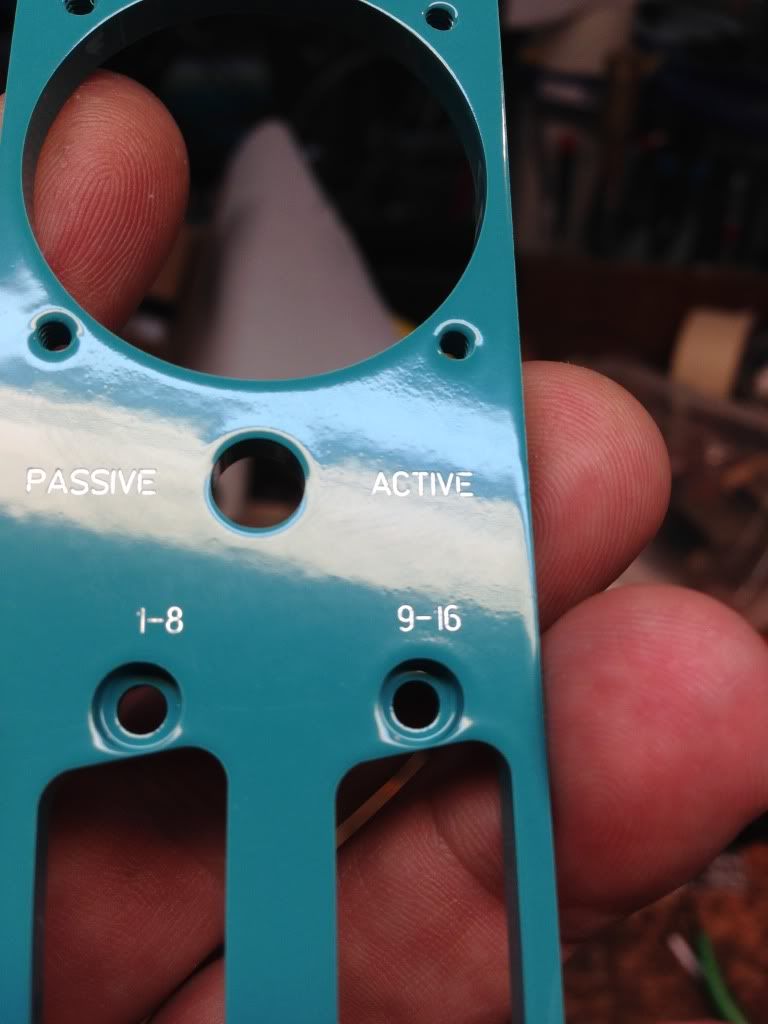
FPE offered to fix it if I send it back, but I may just live with it, I can see the engraving. But it would be a lot clearer in white.
I have updated the file to infill engraving in the attached file (As before rename to fpd). Other than that it seems to fit very well.
Other than that it looks pretty good. I expanded the PASSIVE ACTIVE and other small text.
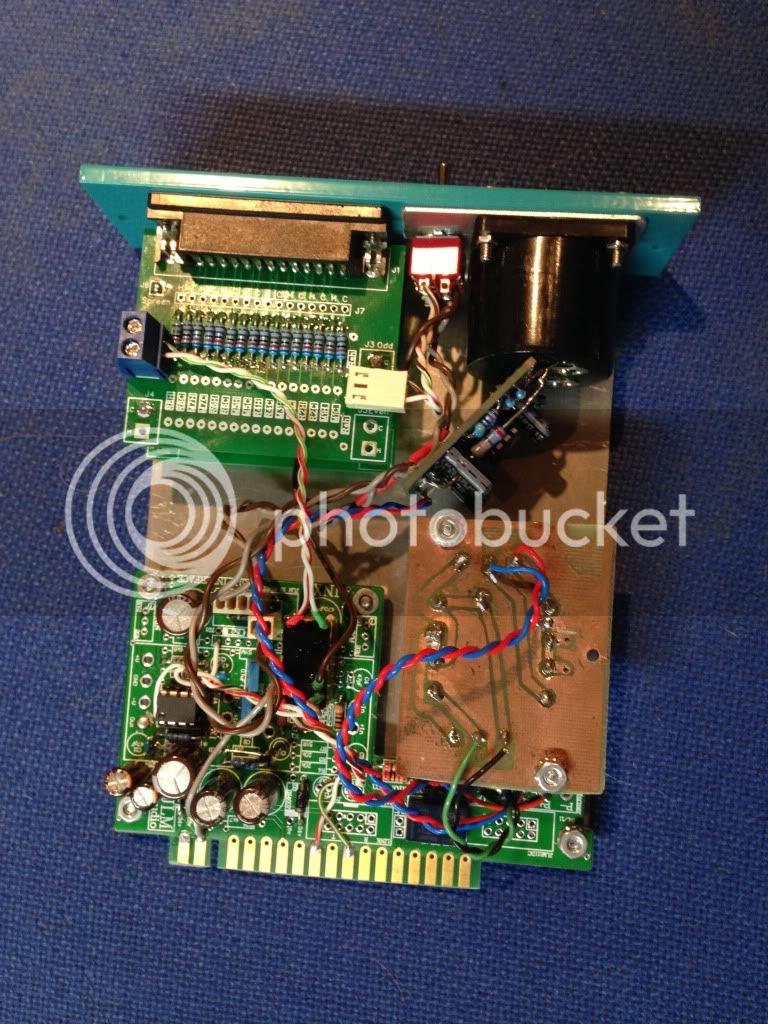
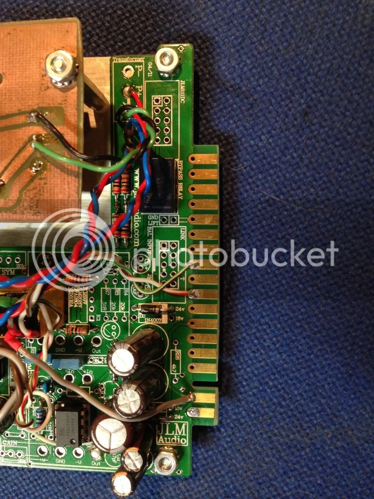
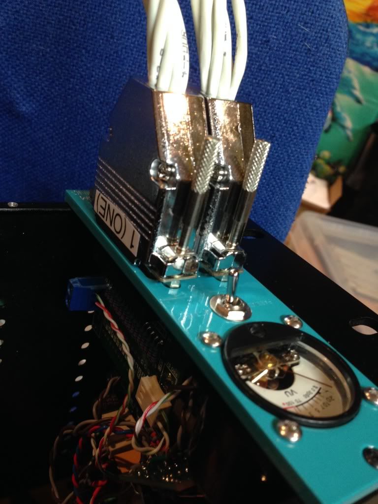
In the next two photos you can tell that I had to cut the gold fingers on the INX5 board. JLM drills the holes in an odd spot, and it was easier than moving all the holes on the L Bracket. It is a tight fit but it just fits.
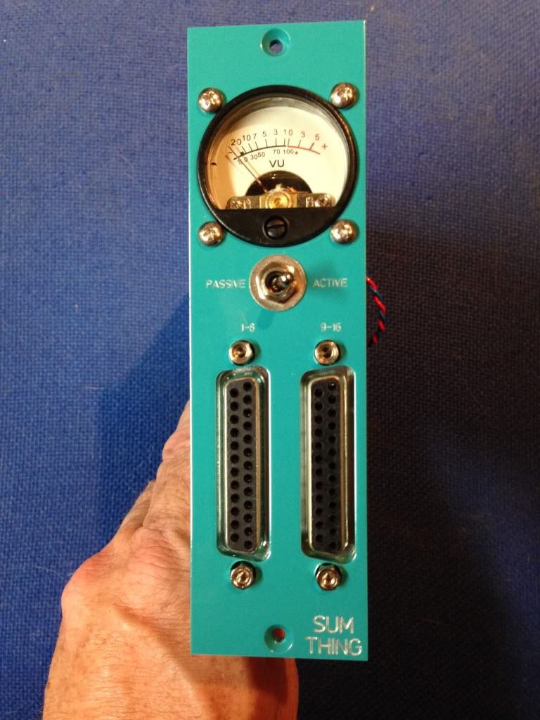
The front panel is very thick 4MM but it makes a nice solid mount for the DB25's. Might work as 3MM. In the attached file I rounded the front corners of the panel with a 1mm radius, and rounded to corners as well. I also increased the 34mm hole to 34.2mm (Because it was easy to pop the VU meter apart because it is so snug).
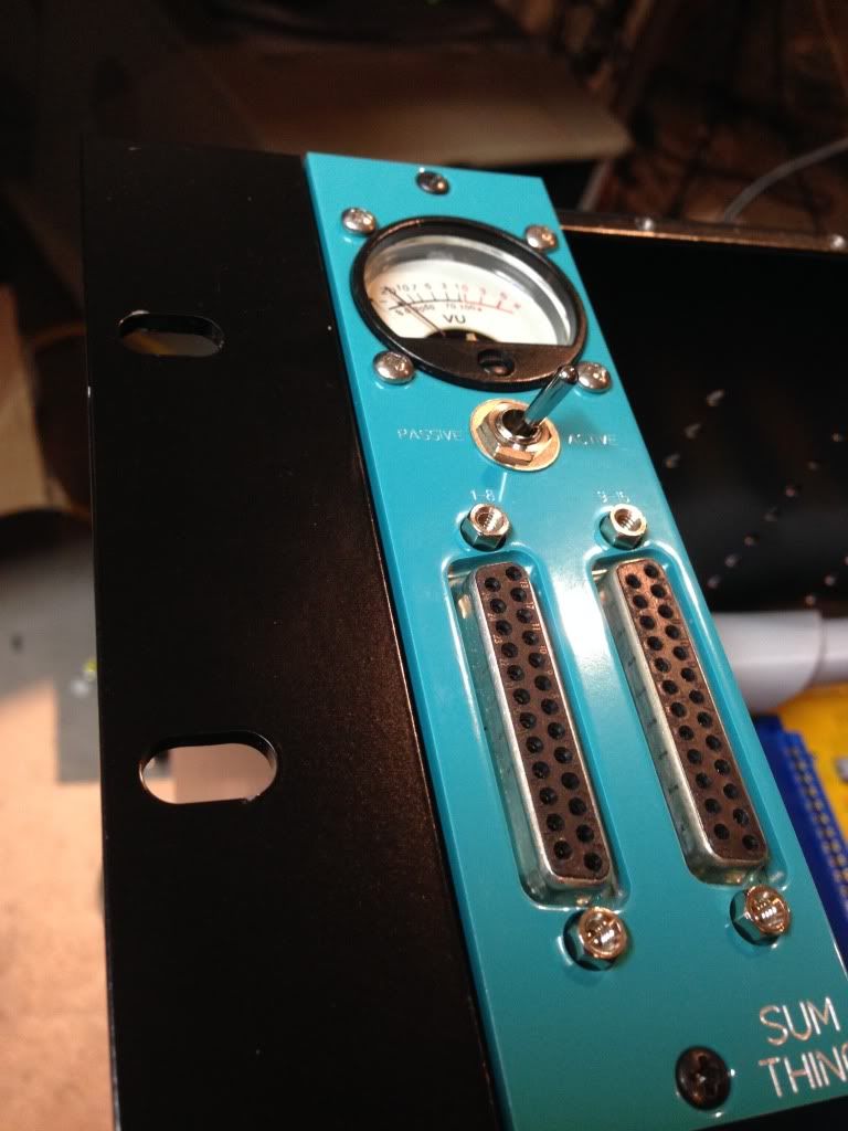
If you do make one of these, make sure you try it out with your DB25 "Shells". I don' think there is a standard for these and some are really thick. These are part of Pro Co Tascam cables, and fit without touching each other or the next module.
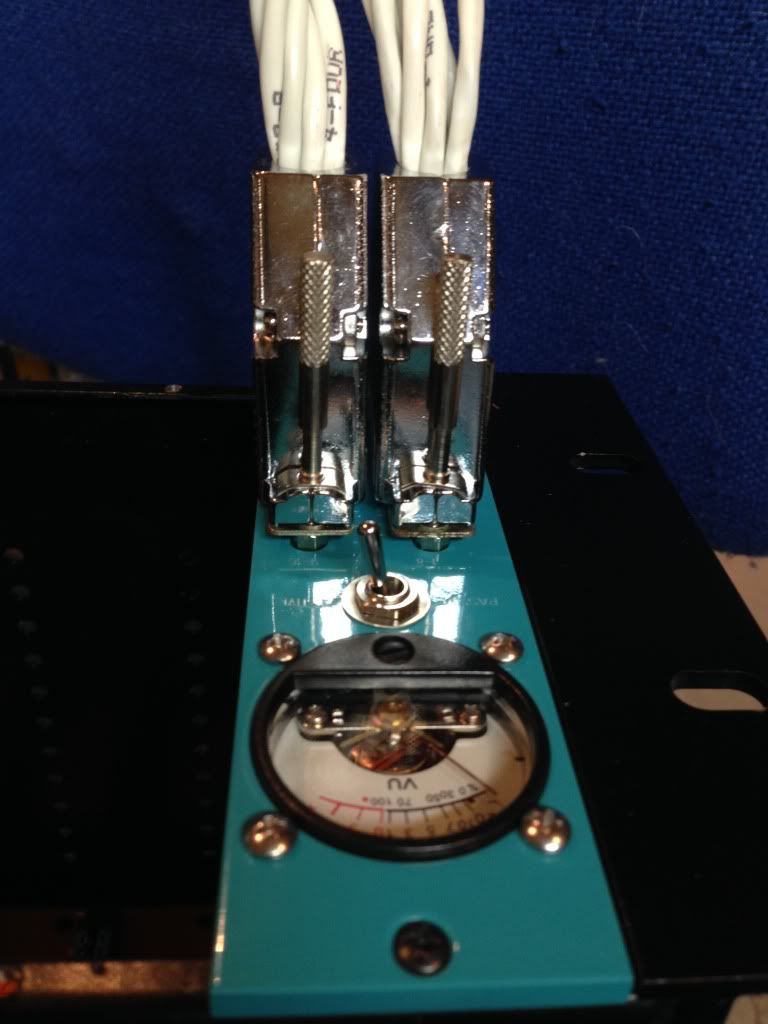
I had FPExpress drill the DB25 Jack screw holes twice to mount them right. That worked perfectly.
FPE offered to fix it if I send it back, but I may just live with it, I can see the engraving. But it would be a lot clearer in white.
I have updated the file to infill engraving in the attached file (As before rename to fpd). Other than that it seems to fit very well.
Other than that it looks pretty good. I expanded the PASSIVE ACTIVE and other small text.
In the next two photos you can tell that I had to cut the gold fingers on the INX5 board. JLM drills the holes in an odd spot, and it was easier than moving all the holes on the L Bracket. It is a tight fit but it just fits.
The front panel is very thick 4MM but it makes a nice solid mount for the DB25's. Might work as 3MM. In the attached file I rounded the front corners of the panel with a 1mm radius, and rounded to corners as well. I also increased the 34mm hole to 34.2mm (Because it was easy to pop the VU meter apart because it is so snug).
If you do make one of these, make sure you try it out with your DB25 "Shells". I don' think there is a standard for these and some are really thick. These are part of Pro Co Tascam cables, and fit without touching each other or the next module.
I had FPExpress drill the DB25 Jack screw holes twice to mount them right. That worked perfectly.
ruffrecords
Well-known member
@Bruce0,
Can you email me some pics of this to add to my builders gallery?
Cheers
Ian
Can you email me some pics of this to add to my builders gallery?
Cheers
Ian
ruffrecords
Well-known member
I have put all the db25 documentation in a more convenient place:
http://www.ianbell.ukfsn.org/EzTubeMixer/docs/db25/
and I have included a system diagram showing how the db25 card is wired to the 1:10 input transformer on the Twin Line Amp and how its output can be wired to 1K stepped pot at the output.
Cheers
Ian
http://www.ianbell.ukfsn.org/EzTubeMixer/docs/db25/
and I have included a system diagram showing how the db25 card is wired to the 1:10 input transformer on the Twin Line Amp and how its output can be wired to 1K stepped pot at the output.
Cheers
Ian

Audioman
Well-known member

Audioman
Well-known member

Audioman
Well-known member

ruffrecords
Well-known member
It looks like I am just about to sell the last of the second batch of db25 boards. The first batch of 50 I made in May last year sold out right away. The second batch of 50 I had made in June of last year and has lasted 9 months. I am happy to make one more batch if there is sufficient interest. I am not asking for orders, just expressions of maybe I might need a couple in the next year sort of thing.
Cheers
Ian
Cheers
Ian
kpearsall
Well-known member
I will more than likely buy 4 more. At least 4.
mylesgm
Well-known member
I will buy at least 2 but probably more.
Similar threads
- Replies
- 1
- Views
- 212
- Replies
- 7
- Views
- 2K