EZ Tube Mixer Support Thread

GroupDIY Audio Forum

Help Support GroupDIY Audio Forum:

This site may earn a commission from merchant affiliate links, including eBay, Amazon, and others.
Hi Michael,
    Thanks for listening and the nice words, and thanks to Ian for making this possible! I think i cut the low mid on the vocal a bit too much sounds a bit thin...

Regards,

Pierre
 
I have been backtracking all my internal connections and also getting ready to test the 2 module backplane. There is something i have been wondering about. On the 6 module backplane the Phantom OV is tied directly to pin 1 of both the line and mic input and to the console chassis through the connectors.
On the 2 unit backplane the Phantom 0V is tied to the chassis pin 11/12 of the din connector. From what i understand(after restudying the 101 grounding document) the way the 6 module is connected seems to be the right way. I'm wondering how to go about if i want to use the 2 module backplane, since pin 11/12 on my eurocards are not connected to anything...

Regards,

Pierre


Attachments

  • BackplanePhantom.jpg
    BackplanePhantom.jpg
    343.2 KB · Views: 50
Hi Pierre,

Because the 6 module backplane had provision for XLRs, it made sense to connect the phantom 0V to the XLR pins 1. The chassis connection is to allow a good electrical connection to be made to the module metalwork in case this is not achieved by the mechanical fixing of the module to the sub-rack. It's what we used to do a Neve but it is probably not necessary so you could use the chassis bus for something else like another mix bus for example. The point is, the chassis connection is not the 0V of the 48V. I know I connected the chassis bus to the other pin of the 48V connector but the only thing you need to connect to this connector is the +48V. The 0V of the 48V should be connected at the mic input XLRs as in the grounding guide. I apologise for the confusion this has caused. The chassis bus needed to be brought out to a connector somewhere and as it is right next to the 48V bus it was convenient to use that connector.

So, to summarise:

1. Just use the +48V pin of the 48V connector
2. Ignore the chassis connection
3. Connect 0V of the 48V to the mic input XLR pins 1.

Once again I apologise for the confusion but at least your understanding has now reached a level where you can spot these small anomalies. Well done!

Cheers

Ian
 
Good day Ian!
  The confusion is mine please don't apologise!
I just started testing the 2 channel backplane.
I tested with one channel as a line amp  and it works as it should.
Next step will be to check the mic with phantom and a the second channel.
Untill now i seem to be getting better result noise wise but i still need to measure it scientifically.
I like the molex headings a lot. Seem a lot easier to make clean connections and for trouble shooting.
I was wondering if you plan adding it to the emporium?

Regards!

Pierre
 
Hello Pierre,

Glad you like the 2 channel backplane. I only had 10 made initially. The reason was, after I designed it I got 10 made and I still had a mistake in the backplane connector position. With Holger's help I fixed that but I was still nervous about getting many made, so I only got 10 more.  Also, the design has silk screening on both sides - on the back for labelling all the Molex conns. To save money I only had silk screen on one side. Fortunately these turned out OK so now I need to have some made with silk screening on both sides. I just got a special offer from one of my PCB suppliers so I think I'll get some more made and add them to the emporium.

Cheers

Ian
 
I have just been sorting out all the Grayhill switches on the channel amps for the 4 into 2 demo mixer I am building. Since the 71 series Grayhill switches I use are all adjustable, you have insert one or more pins in the right places to stop the switch down to the number of positions you need. Even if you use all 12 available positions you still need to add a pin if you want to stop the switch going from position 12 to position 1. Fortunately, every time I have used the Grayill 71 series switches. I always laid out the PCBs starting from pin one so that if any positions are left over they always start at 12 and work downwards. This means I have one standard way of adding the stop pins to the Grayhills that only varies with the number of positions you need to end up with. I worked this all out last night when I added all the pins to the mic gain and EQ switches in the 4 into 2 demo mixer. The document attached shows how to get the number of positions you want and also how many positions you need for each use of the grayhill 71 series in the EZ Tube Mixer.

Cheers

Ian
 

Attachments

  • GrayhilStopsscaled.jpeg
    GrayhilStopsscaled.jpeg
    419 KB · Views: 0
Last edited:
Hi Ian,
  Thats gonna be really usefull, thanks a lot Ian. I had noted the pin positions but lost the paper somehow.

Regards,

Pierre
 
anjing said:
Hi Ian,
  Thats gonna be really usefull, thanks a lot Ian. I had noted the pin positions but lost the paper somehow.

Regards,

Pierre

I am always losing bits of paper; that's why I try to put everything on the web - much harder to lose!!

Cheers

Ian
 
Switches:

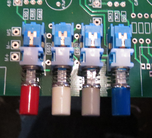
Ian has designed the EZ main board for ALPS SPUJ190900, but it is also possible to use C&K PHA2UEE.
C&K has some coloured round caps which fit on the  ALPS also.


small-switches.jpg


Nice one Holger. The rectangular caps are in very short supply, especially the coloured ones. I like the nice large gap between the round buttons as well. This should make front panel layouts simpler as well.

Cheers

Ian
 
Holger put my attention to this project some time ago and I must admit that some really good work has been done here already.
Makes me want to built one of this mixers with some Pultecs for myself as soon as time allows.  :-\

@ Pierre: This is f_%$_ing awsome and still shows that there is only a handfull of good equipment as well as a godd artist needed... really appreciated.. I like the dynamics. Even works on crappy laptop speakers!

Regards,

Christian
 
@Holger, are you revisiting you faceplate design?

@Ian, I did find some rectangle c&k that came in red, i'll try to find them for the part number.

@Christian,  the nice thing with this project is because it's modular you get to use it while building it. The ez-tube preamp is definitely something you want in your recording chain...Thanks for the nice words.

Regards,

Pierre
 
Still no news from digikey for the 168hp rails, i'm thinking of changing the concept to a smaller 84hp wide slim console.
Funds are rather low so i could make do with what i have and the studio is a bit cramped so a smaller footprint would be wiser.
Here are a few sketches of how i would about it.
19eztubeconsoleREV1.jpg

19eztubeconsoleREV2.jpg

The subracks would be held together by wood side cheeks.
Sure would not be as nice as the wide format prototype.

What are you guys using for molex connectors? Are you using original or generic?
I bought original molex terminals bulk i'm getting frustrated when i try to cut them away from the stripe without squashing them....
molex.jpg


Regards,

Pierre


looks really nice, Pierre,

but one thing comes to my mind seeing the mixer in 3D representation: how much total will you dissipate and do you have a concept for that? I think that might be crucial in the end to do a analysis of that because it might have a significant impact on the final design.

- Michael
 
Thanks Michael,
  Good point! I will do a prototype with cardboard cheeks to monitor the heat, i was planning on having the top half  of the connectors panel closed with a schroff shield panel that has vents. The lower modules will probably be the ones to watch.

Regards,

Pierre
 

Latest posts

Back
Top