FET "Grinder"

GroupDIY Audio Forum

Help Support GroupDIY Audio Forum:

This site may earn a commission from merchant affiliate links, including eBay, Amazon, and others.
Dr Gris said:
It looks to me as that could be done in a 1RU case, or no?

By design, yes - but it has not been verified in real life conditions :)

Gustav
 
Gustav said:
My mailbox is the same. I have begun to assume that no answer = problem fixed :)

Gustav
Still want to know it.For myself I'm nearly a 100% sure that it was the issue,and a signal will have passed up the mentioned r27,just a few passive parts in the chain.

Anyway,no reply might say problem fixed,but doesn't help other builders.

Best,

Udo.
 
Ahhh!!!  Yes no jumpers.  Sorry I run a bar/restaurant so my weekends (especially summer) are... well they are spent there 24/7 unfortunately.  So I was able to see what Gustav had responded just before going to work (I can't tell you how frustrating that was) and then dropped my head  in confusion cause it seemed I should know this but I am afraid i don't.  I have no idea what you mean by jumpers and so no I never installed them. 
 
Rocinante said:
Ahhh!!!  Yes no jumpers.  Sorry I run a bar/restaurant so my weekends (especially summer) are... well they are spent there 24/7 unfortunately.  So I was able to see what Gustav had responded just before going to work (I can't tell you how frustrating that was) and then dropped my head  in confusion cause it seemed I should know this but I am afraid i don't.  I have no idea what you mean by jumpers and so no I never installed them.
O.K.,good to hear!
For jumpers just use leftover legs from diodes or capacitors or whatever you prefer,it's just a conducting bridge over the corresponding tabs.
Check the transistor orientations for a hopefully final time,fire it up and measure the beforementioned control points.Let us know then please.

Good luck,

Udo.
 
kante1603 said:
Rocinante said:
Ahhh!!!  Yes no jumpers.  Sorry I run a bar/restaurant so my weekends (especially summer) are... well they are spent there 24/7 unfortunately.  So I was able to see what Gustav had responded just before going to work (I can't tell you how frustrating that was) and then dropped my head  in confusion cause it seemed I should know this but I am afraid i don't.  I have no idea what you mean by jumpers and so no I never installed them.
O.K.,good to hear!
For jumpers just use leftover legs from diodes or capacitors or whatever you prefer,it's just a conducting bridge over the corresponding tabs.
Check the transistor orientations for a hopefully final time,fire it up and measure the beforementioned control points.Let us know then please.

Good luck,

Udo.

Thank you.
 
YYYEEEESSSSSS!!!!!!!!!!!!!

It works.  Input, Output, compression.  Thank you Udo
Thanks for seeing that Gustav.
I was beginning to go crazy.

Whew.

Okay so I feel pretty foolish not putting that together myself.  The psu is on board. duh.  I had searched using  many variations; 1176, jumper, +30, etc... but the Mnats board layout is just different enough.  I just wasn't seeing it.
Okay so now to watch some videos on calibrating this guy.

Thanks again guys.
:)
 
Gustav said:
kante1603 said:
Hi Gustav,

it seems that the jumpers aren't soldered it in your assembly guide,at least I can't see them.
Maybe he followed the build giude pics a tad "too precise....."? ;D

Cheers,

Udo.

Yep, maybe I thought it would be obvious, which of course, it isn't.. Ill get it added to the guide, when I have some time to do the file rendering/Change the file on the server etc.

And it would still be great to know if this is the actual problem :)

Gustav

Sorry just for clarity your talking about the two beside the lundahl output transformer.? -10 and +30?  I thought it was weird those were left blank, but I too copied the guide too closely

Also, is it going to be a critical thing if the mains in my house are a little high? Pending on the last couple days I've been testing this project the secondary of my toroid read 28-30.5v ac. Is this terrible for any of my psu components? I know for the gssl it made my rectifiers run a little hot... I just added larger heat sinks...

Do bd139 and bd140 need to be bolted to the chasis or is it not mandatory?

Thanks in advance.
 
Orchid0 said:
Gustav said:
kante1603 said:
Hi Gustav,

it seems that the jumpers aren't soldered it in your assembly guide,at least I can't see them.
Maybe he followed the build giude pics a tad "too precise....."? ;D

Cheers,

Udo.

Yep, maybe I thought it would be obvious, which of course, it isn't.. Ill get it added to the guide, when I have some time to do the file rendering/Change the file on the server etc.

And it would still be great to know if this is the actual problem :)

Gustav

Sorry just for clarity your talking about the two beside the lundahl output transformer.? -10 and +30?  I thought it was weird those were left blank, but I too copied the guide too closely

Also, is it going to be a critical thing if the mains in my house are a little high? Pending on the last couple days I've been testing this project the secondary of my toroid read 28-30.5v ac. Is this terrible for any of my psu components? I know for the gssl it made my rectifiers run a little hot... I just added larger heat sinks...

Do bd139 and bd140 need to be bolted to the chasis or is it not mandatory?

Thanks in advance.
1. Those are the ones, yes. You should measure your voltages before you jump them.

They are there to separate the PSU section from the rest of the circuit until you have verified your PSU is working correctly.

- Unfortunately, they will also cause the unit not to work, if the designer did not document the project correctly :(

2. I would not worrie about high mains, but check that the regulators are not over worked/see what you get on your secondaries.

3. Install BD139 and BD140 on the PCB as shown in the guide. No need to bolt.

Gustav
 
Hello,

I was about to answer at the same time,but Gustav was faster ;D
About your ac voltages measured at the secondaries directly (?),they will go down once they are connected to the psu circuit.
Then measure the dc voltages (30 &-10) at the pads with reference to ground (psu 0v) without the jumpers installed.If all is good you can put them in as Gustav said,then bias,adjust and test the baby.

Best,

Udo.
 
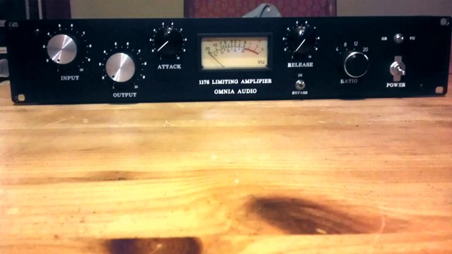
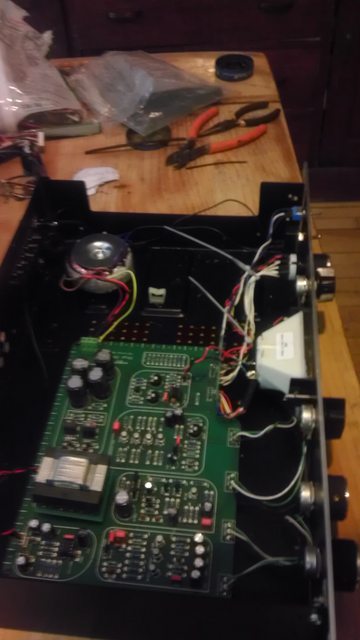
Yeah so I have been using the phet 76 and I gotta say it is really great.  I am gonna go back and calibrate it a little better but so far I feel  it certainly has that familiar 'drive' I like in my other 76's.
Anyways here's a few pics. 


I do have one little problem though.  I can't for the life of me figure out where to tap for the 5v i need to power the vu meter led's any suggestions?  It's one of the nissei tn-73 kind. 

Thanks again for the project Gustav.  Great fun.

Cheers
 
Rocinante said:
I do have one little problem though.  I can't for the life of me figure out where to tap for the 5v i need to power the vu meter led's

Straight from the trafo secondaries with a drop resistor, or since its just an LED, straight from the -10V jumper with a drop resistor.

Gustav
 
Hello, finishing this one, I m looking for the configuration of the two switch, I would like to mount it as it as been designed (screwed on front panel) for more conveniency, but I ve ordered seral switches which I suppose to be SPDT and DPDT (not mentionned in the bom but what I concluded because of their action on the circuit ? )

Can get one with same height as the  Lorlins ( screw is too short) also it's really hard (I didn't try to be too brutal) to push the pins through the PCB, I think I all have to cut some part of the pins anyway.

Also I don't feel confortable with those small toggle switch if you have any suggestion for a bigger one that would still mount to the pcb ?

If somebody have solved that kind of issue please let me know.

thank you

 
Hi,

Yes! What kind of switches please? SPDT DPDT... ON/ON, ON/OFF?
A ref for the round diode bridge?

Thanks
 
p0ulp said:
it's really hard (I didn't try to be too brutal) to push the pins through the PCB, I think I all have to cut some part of the pins anyway.

PCB pins or solder lugs on the switches? This would make a big difference (no problem here pushing switches though the PCB, which is why I ask(

p0ulp said:
Also I don't feel confortable with those small toggle switch if you have any suggestion for a bigger one that would still mount to the pcb ?

Toggles come with all sorts of paddles. You can find some pretty wide ones if you care to wade through mousers catalog for them.

Gustav
 
kustohm said:
Hi,

Yes! What kind of switches please? SPDT DPDT... ON/ON, ON/OFF?
A ref for the round diode bridge?

Thanks

DPDT and SPDT, both ON/ON

Diode bridge should simply be sufficient to handle the voltage/amperage of the project. Higher will do as well.

Gustav
 
got a pair of the Phat Phet boards (they look great, very nice layout, thanks Gustav!) I'm hoping to build a stereo unit - which components do I need to match and how closely, for the best stereo image possible?


also has anyone done any resistor charts for switched versions?


lastly, should i build them in separate boxes to avoid interference, or will they work fine in a single 2 or 3U box?
 
miszt said:
got a pair of the Phat Phet boards (they look great, very nice layout, thanks Gustav!) I'm hoping to build a stereo unit - which components do I need to match and how closely, for the best stereo image possible?

Matching FETs and pots would be most critical, and you'll need to search for the stereo link and build that into it and check the 1176 schematic on where to tap it from the board, since it was not designed into it,

miszt said:
also has anyone done any resistor charts for switched versions?

You would have to come up with it yourself, if you want to do that .

miszt said:
lastly, should i build them in separate boxes to avoid interference, or will they work fine in a single 2 or 3U box?

A channel will fit into 1RU, and I would advice you to build two separate units.

Gustav


Latest posts

Back
Top