FET "Grinder"

GroupDIY Audio Forum

Help Support GroupDIY Audio Forum:

This site may earn a commission from merchant affiliate links, including eBay, Amazon, and others.
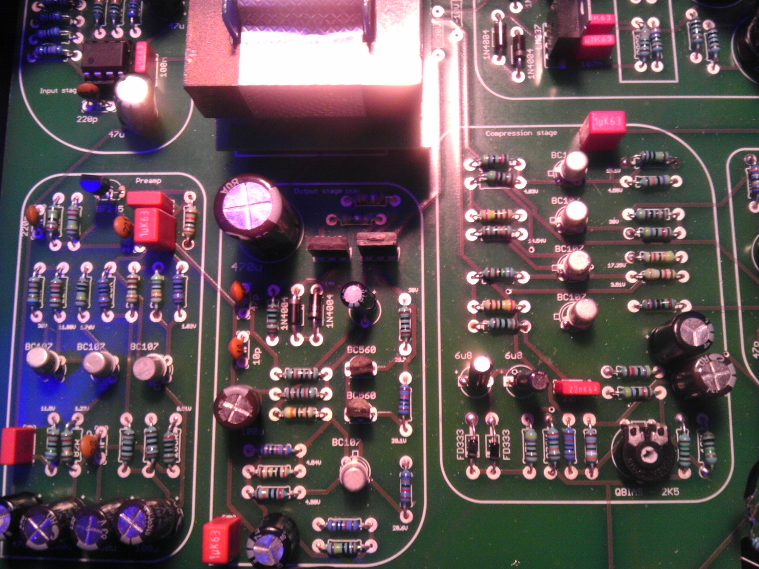
Ok this is getting frustraiting, I´ve check all conections ans solder bolbs and everything is fine, audio signals and V are fine I guess  :-\ i compared with G1176 schem but some components on FET grinder are diferent and wasnt sure what V. should I read.

all the controls except input and output doesnt affect the audio, I cant notice any compression switching ratios, Q-Bias trimmer to start callibrating is not turning it from CW instead from CCW.

Good conection from board to Controls!

O maaaaaaan!! can some one tell me from where start investigating to make this little monster to compress??

Thanks
 
Rocinante said:
..the BF245..
could be any of its subgroups (A, B, C). You want a BF245A for an about -2Vdc cutoff voltage. With a little luck your BF245 might be close enough to this parameter (or not).

..and on one side of the resistor (closest to the input pot) I have a signal and on the other side nothing.
so the FET is conducting, shunting signal down for max.compression. The Q-Bias trim was set correctly ?
About what value resistance is the 'dirt' pot without parts value set for? The distortion trim from original schematic would vary resistance between 150R and 250R with 200R as a typical value of the 150R fixed resistor in series to the 100R trimmer, dialed in about half rotation. As this circuit implementation is missing the fixed value resistor as min.resistance and the dirt pot could be set for zero ohms, this might matter. I never built it.
 
What I would do, if I were having problems with a stereo build, this is where I would start.

1. Isolate one channel.

2. Check voltages

3.If this is the "old" version of the PCB, the voltages around the transistors will still be identical with the schematic with values plotted in. If this is the new version of the PCB, the values around the transistors are printed in the silk screen.

4. If those voltages are good, start tracing the signal through.

5. The trimmer for q bias is reversed from the original, but this just means your starting at the other end, not that is works  any differently.

6. You dont need precision calibration to check if the unit is working, just turn it all the way off and nudge it a little up.

Hope that helps.
 
Gustav said:
What I would do, if I were having problems with a stereo build, this is where I would start.

1. Isolate one channel.

2. Check voltages

3.If this is the "old" version of the PCB, the voltages around the transistors will still be identical with the schematic with values plotted in. If this is the new version of the PCB, the values around the transistors are printed in the silk screen.

4. If those voltages are good, start tracing the signal through.

5. The trimmer for q bias is reversed from the original, but this just means your starting at the other end, not that is works  any differently.

6. You dont need precision calibration to check if the unit is working, just turn it all the way off and nudge it a little up.

Hope that helps.

Hello there,
Old pcb, one unit isolated, All voltage seems to be fine all checked, regulators at PSU getting hot eventually, how do I trace the signal to find the non compression problem??
Thank you
 
Harpo said:
Rocinante said:
..the BF245..
could be any of its subgroups (A, B, C). You want a BF245A for an about -2Vdc cutoff voltage. With a little luck your BF245 might be close enough to this parameter (or not).

..and on one side of the resistor (closest to the input pot) I have a signal and on the other side nothing.
so the FET is conducting, shunting signal down for max.compression. The Q-Bias trim was set correctly ?
About what value resistance is the 'dirt' pot without parts value set for? The distortion trim from original schematic would vary resistance between 150R and 250R with 200R as a typical value of the 150R fixed resistor in series to the 100R trimmer, dialed in about half rotation. As this circuit implementation is missing the fixed value resistor as min.resistance and the dirt pot could be set for zero ohms, this might matter. I never built it.

Thanks for responding Harpo I am sorry I wasn't more clear; it is the BF245B.  I just got some 2n5457's in the mail yesterday so I should probably just throw in those huh?

Okay so I had no idea I had to even think about calibrating anything at this stage (I just wanted it to pass signal) and so I am pretty sure I just set all the trimmers to zero.  Typing that I realize how absurd that sounds (of course it takes it at the input stage) and will make the adjustments you suggested.  Hopefully that is all. 
As far as the "dirt" pot goes there isn't one in the version (Phat Phet) that I am building so no worries there. Thanks for all the suggestions I will begin adjusting momentarily.  Fingers crossed. 
 
Please, can you tell me where should I read if there is good voltage when I switch ratio?? On 1176N they say look mesure V on pad 22 and 21, what a bout FET old unit???

Thanks

Luis
 
Ok for all the new people like me, who want to get the thing compressing instead starting calibrating Q Bias from - to +, start from the maximun you can get when you turn the input up, this way you will get really nice amount of signal, then you can turn the input to reach 0 and then the Q Bias -1db,  mesure AC V betewn pin 2 and pin 3 of the the XRL out with the multimeter to see how much compresion is acting when you switch to GR

now I have to make the meter to tell GR, but fisrt have some fun with it.. ::)
 
Harpo said:
Rocinante said:
..it is the BF245B.  I just got some 2n5457's in the mail yesterday so I should probably just throw in those huh?
Y!, just observe their different pinout.

So (sigh) I replaced the BF245b with a 2n5457 (and spun it 180 in observation of the pin out) and still I have nothing.  Here is a picture of the input stage area where the signal stops.
rbIX3og.jpg


Like I had mentioned before on one side of the 27k resistor (to the right of the 2N5457 and right next to the 1u 63v Wima) I have signal loud and clear.  On the other side it is now faint.  Along with the 2N5457 I hear a slight signal along with 'ground hum'? but barely anything.  I checked the bias and adjusted in every direction possible.  I'm at a loss.  I also probed around other nearby resistors and a few of them exhibit the same barely audible signal while others provided nothing.  Any ideas?


Rocinante said:
Harpo said:
Rocinante said:
..it is the BF245B.  I just got some 2n5457's in the mail yesterday so I should probably just throw in those huh?
Y!, just observe their different pinout.

So (sigh) I replaced the BF245b with a 2n5457 (and spun it 180 in observation of the pin out) and still I have nothing.  Here is a picture of the input stage area where the signal stops.
rbIX3og.jpg


Like I had mentioned before on one side of the 27k resistor (to the right of the 2N5457 and right next to the 1u 63v Wima) I have signal loud and clear.  On the other side it is now faint.  Along with the 2N5457 I hear a slight signal along with 'ground hum'? but barely anything.  I checked the bias and adjusted in every direction possible.  I'm at a loss.  I also probed around other nearby resistors and a few of them exhibit the same barely audible signal while others provided nothing.  Any ideas?

I have to ask again, if you are getting the correct voltages.

I designed the board, so you can check the supply voltages on the PSU before letting them lose on the circuit. This can save you from frying up transistors...

But the -10 and +30 jumpers are not in place on your picture, and if that is the case, your supply voltage should be 0, unless you measure at the PSU section.

The voltages printed on the PCB in reference to the transistors are approximate, expected values with reference to ground. You can use the middle pin of the 3 pin connector, if you dont know where to find a ground reference.

I hope that brings you a step closer.

Gustav

 
Hi Gustav,

it seems that the jumpers aren't soldered it in your assembly guide,at least I can't see them.
Maybe he followed the build giude pics a tad "too precise....."? ;D

Cheers,

Udo.
 
kante1603 said:
Hi Gustav,

it seems that the jumpers aren't soldered it in your assembly guide,at least I can't see them.
Maybe he followed the build giude pics a tad "too precise....."? ;D

Cheers,

Udo.

Yep, maybe I thought it would be obvious, which of course, it isn't.. Ill get it added to the guide, when I have some time to do the file rendering/Change the file on the server etc.

And it would still be great to know if this is the actual problem :)

Gustav


Would it be possible to squeeze two boards side by side and fit two small VU's in a 1U rack?
If not, maybe if pots are off board?

Best
//Magnus
 
Dr Gris said:
Would it be possible to squeeze two boards side by side and fit two small VU's in a 1U rack?
If not, maybe if pots are off board?

Best
//Magnus

If you want a stereo unit, I would recommend the 1178/Symmetrical FET. I doubt you can fit two of these in a case, even if you wire the pots and switches.

This board is designed with beginners and ease in mind. Big layout, a lot of space, clear sections etc. For a tighter fit, I would recommend using the Gyraf/Mnats boards.

You could do two channels in a 2RU case on top of each other -  https://pcbgrinder.com/index.php?route=product/category&path=106_117

Gustav

 
Well I was thinking dual mono in 1RU just to save space.
And your boards look so good and would make it easy to troubleshoot if I mess up, since I'm a beginner after all  8)

As a matter of fact I've been keeping an eye on your Symmetrical FET as well.
It looks to me as that could be done in a 1RU case, or no?

Best
//Magnus
 
Back
Top