Gates 28 CO New Build

GroupDIY Audio Forum

Help Support GroupDIY Audio Forum:

This site may earn a commission from merchant affiliate links, including eBay, Amazon, and others.
Alex,

The basic Bridge idea is explained here:-

http://en.wikipedia.org/wiki/Wheatstone_bridge

The lamps are the top resistances and the 7.5 ohm resistors are the bottom pair.

The signal is taken across the middle (where the Wiki picture meter is shown).  When the legs are in perfect balance, there is no voltage difference at this point so the signal is very low, when the resistance of the legs is different there is a voltage difference and audio is passed.

L' Andratte,

I'm glad someone wants to continue the art! ;D

best
DaveP
 
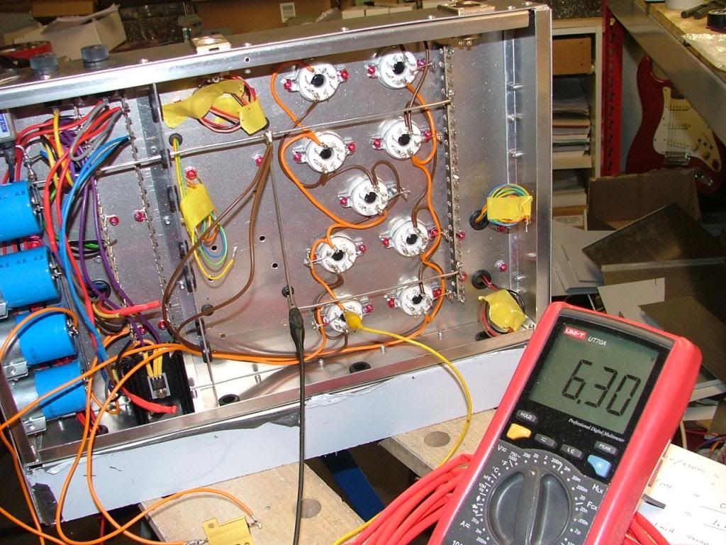
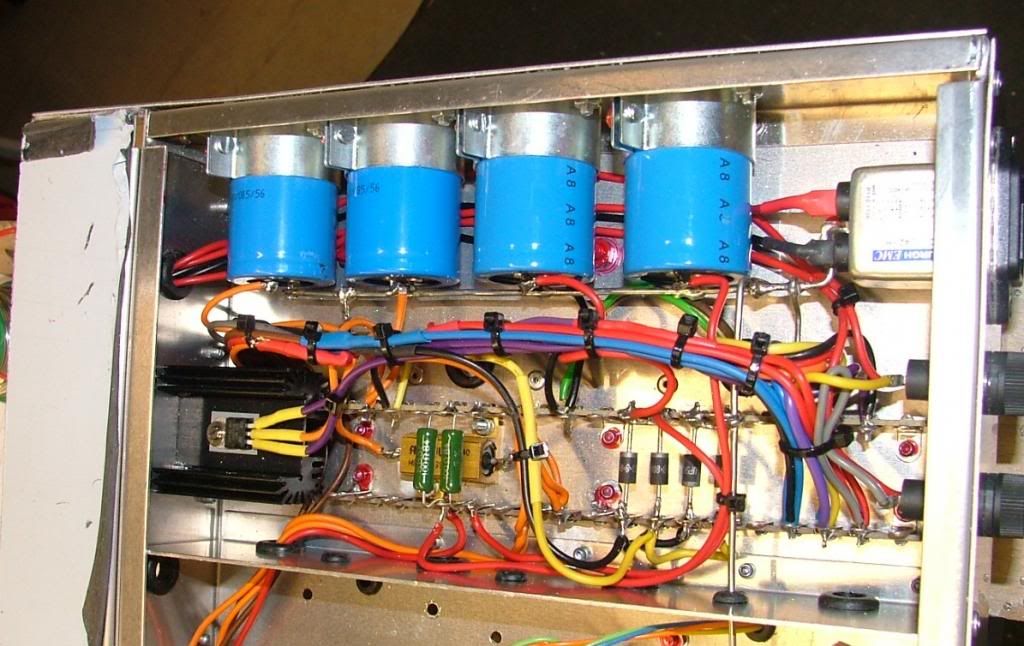
Not much to show for two evenings work, the wiring up always slows things down.  The heatsink for the heater supply tucks in neatly, its probably not necessary but best to be on the safe side with 4 amps through it ;)

The heater supply is finished and works very well, Voltage came out spot on  8)


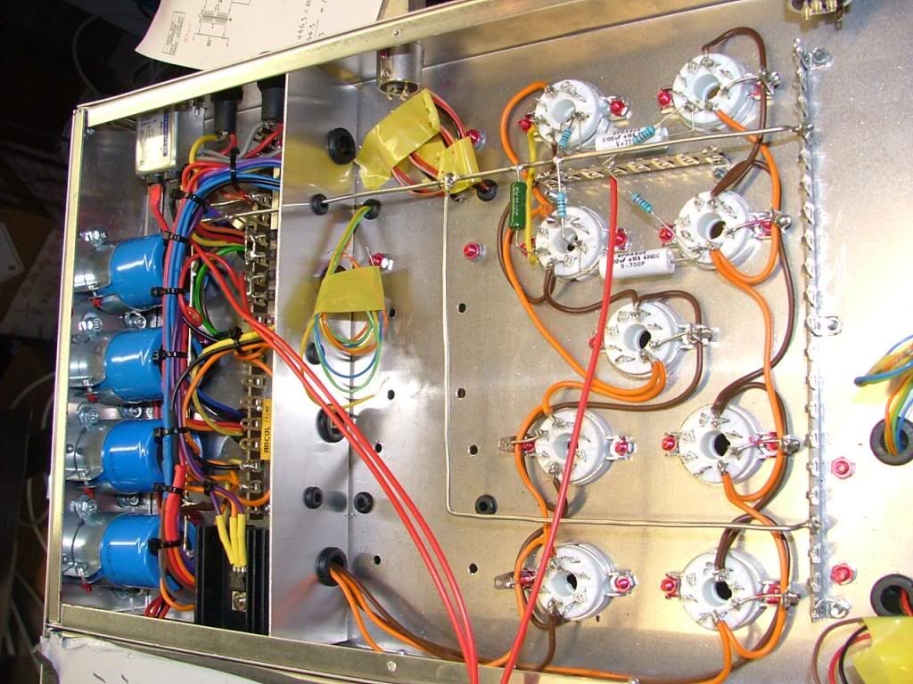
Busbars are fitted as are some tag strips, more will be needed around the tubes, wiring will have to be tidied up but this gets the heater supply out of the way.  I extended the transformer wires as necessary and covered the joins in heatshrink


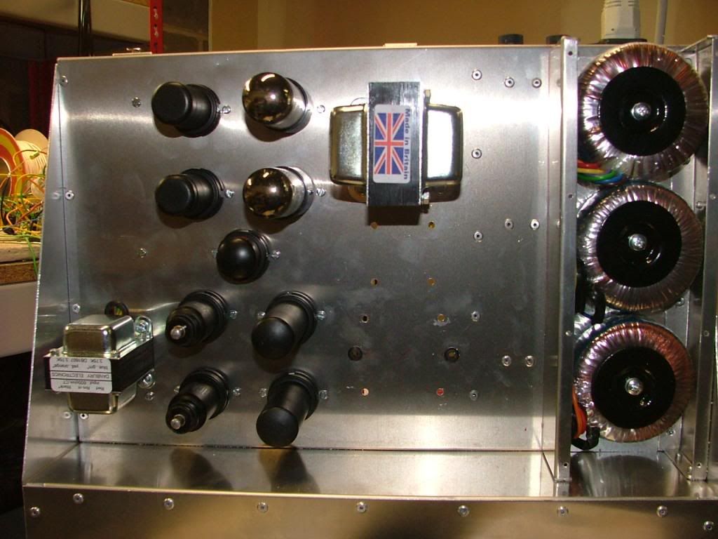
All the tubes are in on the other side looking like Octal Heaven. :)
Next job is the B+ and then that will be the power supply finished and then on with the amps.

best
DaveP
 
I've tidied up the power supply wiring....amazing what a few cable ties will do.
Also found a home for the 25W Al clad heater dropper and fitted the HT bridge rectifier.


Assembling the make up amp now, very few components in these old designs.
More next week
best
DaveP
 
Wow, cool stuff!
I have a stupid newbie question, I'm looking at the busbars connected to the tag strips,
that in turn are connected to chassis.
Anything to look out for by doing that?
Just thinking about what you said earlier about isolating them.
Or maybe I'm looking at this the wrong way?
I'm only trying to learn, and your build threads are golden!

Cheers
Magnus
 
Magnus,

Maybe the pics are not very clear, the support tags are fixed to the chassis but none of the others are and the busbar is fixed to some of those.  The busbar also passes through a grommet in the chassis screen.

Thanks for the support
best
DaveP
 
Another week, another amp.
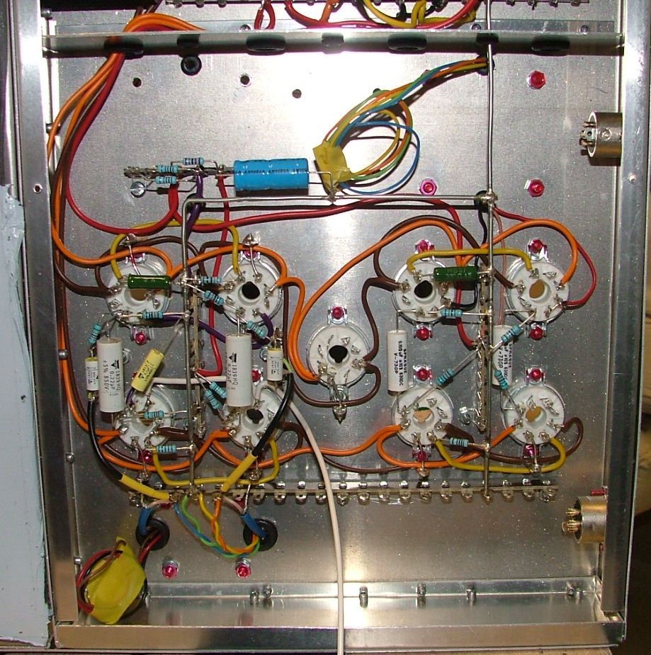
This is the input amp finished.  The only difference between this input amp and the original is that the feedback caps are 47nF instead of 10nF.  This cap decides the bass response (small cap equals less feedback equals more bass) and has to match the input transformer used; I'm using a modern transformer.


I've used polyprop caps throughout for the audio, this amp was quite fiddly to do because of the feedback loops, 4 connections to one octal socket is pushing it.

Colour code I always use is Yellow for cathodes, purple for grid 2's, Orange for 6.3V, white for CV, red for HT. Brown or Green for heater earths, Blue for plate/anodes.

I fired it all up last night and all the voltages are ok so I was able to settle on the dropping resistor for the B+/HT.  This worked out at 200 ohms and as its passing 135mA (3.6W) I decided to split it by using two 100 ohm resistors 7W types.  They are positioned under the 25W Al clad (when its the right way up) so it will act as a heatsink for them too.


Finished Power Supply all tidied up.  In the end I only used half of the grommet holes, but it's impossible to put them in later so best to be generous before you start.  This is a new type of B+ supply for me, I used two 470uF caps so the rectifier diodes are UF5408 types to be able to handle the inrush current on start up.  Because of the size of these caps, the HT doesn't come on instantly but builds over a couple of seconds.  This level of smoothing is better than the two chokes and 3 small caps in the original 28CO.

I still have to connect the 6H6 but that is more involved with the front panel, which I'm starting on tonight.
best
DaveP
 
Looking very nice, Dave.

I was wondering about the big-pi filtering vs lesser-pi with chokes.
Sounds like it can work well. I'm considering that approach for my next build.

And without a slow starting tube rectifier, the inrush current into all those reservoir caps can surely get quite sizable - I suppose a good size fuse will be required as well.

Anyway, you're well on the way :)

Regards
 
I'm simply spellbound buy this build , just incredible !!  I hope to one day be able to do something like this , and your build documentation and pictures will ensure I have a chance  ;D

  ... one question ( for now )  ;D  that thick ground wire / ground bus / bus bar - where do you get that ? 

    great passion , Thanks !! 
 
I get it from RS in the UK

http://uk.rs-online.com/web/

Part # 390-527

I hope you do carry on the P2P tradition Audiophreak

best
DaveP


Thanks Dave,
                  I'm trying ... my first P2P was a quad of NYDave onebottles that sound great but fell short of an " elegant " build. I could have planned the layout better  and wiring  was a challenge  but all in all, I thought was a good first effort.  I am now starting a Dual Mila P2P and naturally wanting to improve as much as possible.

  Thank you for sharing and documenting this wonderous art form,
                                                                                                    Chip


Well, there has been a break because we sold our house and had to move out. :(

This has been an all consuming and exhausting experience that we have not done for 18 years and have long forgotten how hard it was. :eek:

Anyway, I am now back on the case and looking forward to getting on with the job. :)

More over the next two days.

best
Davep
 
I'd like a few opinions on the layout of the front panel.

Here's an asymmetric look that keeps audio away from the power switch, it also borrows from the original


This is the symmetric look


Any comments or preferences?

best
DaveP
 
Asymmetric.  Looks like more serious work being done by more serious men.  Don't apply if you're not serious about this.  I'm not kidding. 
 
The Democratisation of DIY ::)

A fifty fifty split sounds like reality.
Oh well, the builder gets the casting vote and I've decided to go with serious, this is the final look with the main controls given a touch more room.


The 28-CO logo is the original typeface blown up, how I'm going to get that appied is another matter :-\

So tonights job is to cut all these holes and make it reality.

best
DaveP
 
late reply but I like asymmetrical better. Besides function, I think it looks more organized and as a "composition" draws the eye across the panel more elegantly.
 
Thank you Gato  :D

You have tipped the balance and I now feel I have made the right choice.

best
DaveP
 
Who makes that kind of chassis... or did you DIY it?

The build looks incredible; asymmetric all the way.
 
Thanks Dylan,

Its DIYed from the biggest one of these boxes.

http://cpc.farnell.com/jsp/level5/module.jsp?moduleId=cpc/256377.xml

best
DaveP
 

Latest posts

Back
Top