GSSL HELP THREAD!!!

GroupDIY Audio Forum

Help Support GroupDIY Audio Forum:

This site may earn a commission from merchant affiliate links, including eBay, Amazon, and others.
Hi,

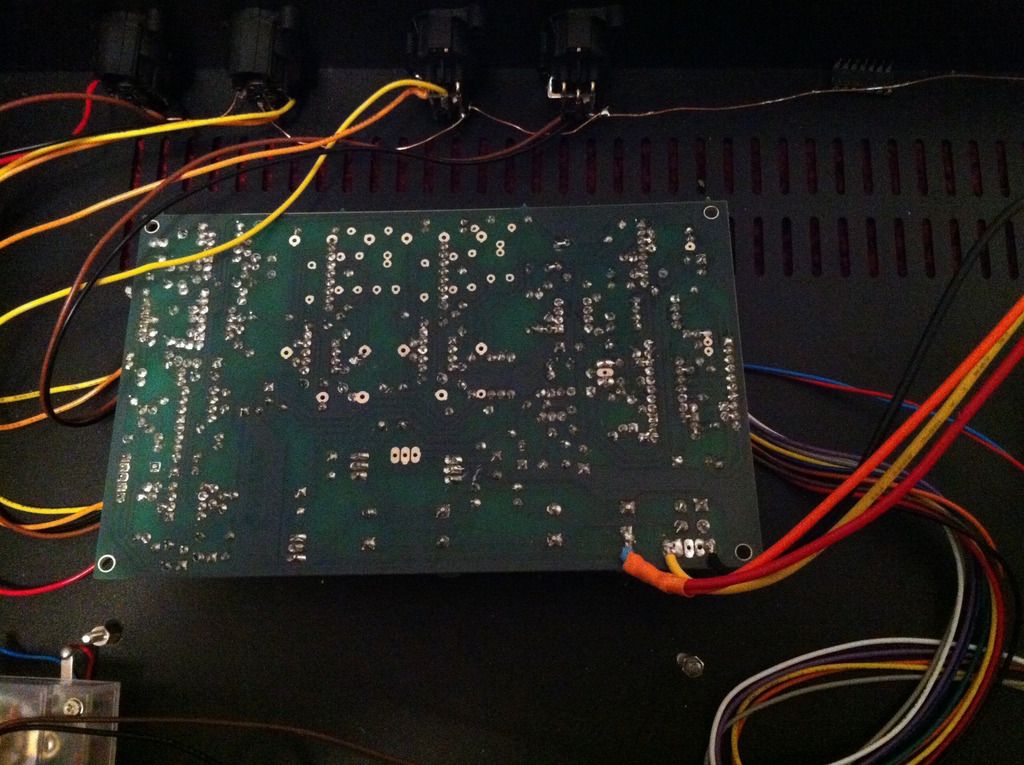
First of all, I need to state that I kind of have no idea about electronics except that it's a big (fun) puzzle... The attached pictures are of the current physical state of my compressor.  When it worked, the compression was present.

Issues:

1. There is a burned 10 ohm resistor. I've replaced that 3 times and same result. Somebody replaced with a 3W one and the unit worked, but with the bellow issue. Anyway, I believe the burning of this resistor is an effect of another issue, but I can't figure it out...

2. When it worked with the 3W resistor, there is a very high buzz. If I disconnect the ground from the power then the buzz quiets down, but still present.

Any suggestions here please? Thank you!

Kind regards,
Alex

Ps: I don't have a meter yet, I still need to search this topic and find a suitable model and a place where I can buy it from - if I can make the unit work properly!
 

Attachments

  • IMG_4248.JPG
    IMG_4248.JPG
    1.4 MB · Views: 65
NoName said:
Any suggestions here please?
You probably fitted 7812  and 7912 type voltage regulators instead of the wanted and different pinout 78L12 and 79L12 types for the +/-12VDC operated sidechain part of the circuit.
 
@ Harop. Thanks. Actually I have L7912CV (G409Q CHN 232), L7812CV (G407V CHN 218).

edit: @Harop, thanks. Quite strange that L7912CV is not equal to 79L12, ist't it? just my rethoric... I'll buy tomorrow the right components..  Thanks again!

edit2: all good now, as the 79L12 and 78L12 did the trick. A very, very low buzz is still present at extreme settings (highest gain makeup and treshold) but barely noticeable. I'll install the meter these days as well. Thanks again Harop!
 
Gustav said:
bxt403 said:
I don't see how shorting the centre tap wires to a single cable that's soldered to the middle pad is going to make a difference

Me neither - I just wanted to make sure you didn't end it in the heat shrink (thats what it looked like on the picture to me).

I also failed to realise you had done another board, and you are now passing audio, but just not getting compression.

Meter kick is normal on start-up, and if it kicks up, you have it connected correctly.


1. I would double check the SC high pass point (fastest way to do it is to solder a jumper from side to side on it to exclude the switch as the culprit).

2. I would double check the wiring of the bypass switch.

Since youre passing audio, I dont suspect you have any problems with your supply voltages, but just to make sure, measure the supply voltages on the ICs (not in and output pins, but voltage supply pins).

Gustav

A wire to the bypass switch was reversed (which I corrected). 
I also shorted the SC switch (which had no effect) and beeped out either side of the SC toggle switch.  The switch seems to be okay. 
I've replaced the TL072 with a T.I. TL072CP and TL074 with a T.I. TL074 but there's no difference from the stock UTC ones that came with the PCB Grinder kit.

The control voltage and the TL072 pin 1 output is corresponding to the THRES pot adjustment (i.e. it's ~-100mV at minimum and around +3V at max). 

I'm still getting the same result: the meter isn't responding (albeit it does jump a bit when I power on/off), only the GAIN pot is the only thing that has any effect while the BP toggle works as it should (i.e. the volume turns much lower when I enable the bypass setting), and the SC chain switch has no effect. The output is stereo and sound is being outputted when I'm feeding a signal in.

I've touched up every solder point in the side chain- so am wondering if I'm just better off installing the turbo mode (as I've read that tends to cure the problem of no compression occurring).
 
bxt403 said:
Gustav said:
bxt403 said:
I don't see how shorting the centre tap wires to a single cable that's soldered to the middle pad is going to make a difference

Me neither - I just wanted to make sure you didn't end it in the heat shrink (thats what it looked like on the picture to me).

I also failed to realise you had done another board, and you are now passing audio, but just not getting compression.

Meter kick is normal on start-up, and if it kicks up, you have it connected correctly.


1. I would double check the SC high pass point (fastest way to do it is to solder a jumper from side to side on it to exclude the switch as the culprit).

2. I would double check the wiring of the bypass switch.

Since youre passing audio, I dont suspect you have any problems with your supply voltages, but just to make sure, measure the supply voltages on the ICs (not in and output pins, but voltage supply pins).

Gustav

A wire to the bypass switch was reversed (which I corrected). 
I also shorted the SC switch (which had no effect) and beeped out either side of the SC toggle switch.  The switch seems to be okay. 
I've replaced the TL072 with a T.I. TL072CP and TL074 with a T.I. TL074 but there's no difference from the stock UTC ones that came with the PCB Grinder kit.

The control voltage and the TL072 pin 1 output is corresponding to the THRES pot adjustment (i.e. it's ~-100mV at minimum and around +3V at max). 

I'm still getting the same result: the meter isn't resending (albeit it does jump a bit when I power on/off), only the GAIN pot is the only thing that has any effect while the BP toggle works as it should (i.e. the volume turns much lower when I enable the bypass setting), and the SC chain switch has no effect. The output is stereo and sound is being outputted when I'm feeding a signal in.

I've touched up every solder point in the side chain- so am wondering if I'm just better off installing the turbo mode (as I've read that tends to cure the problem of no compression occurring).

1. Did you check through the supply voltages to rule it out (eliminating variables is important).

2. I am trying to follow your thoughts on the trouble shooting  - what was your expected "best case" outcome  when swapping the opamps for a different brand?

3. Since you found one error on your bypass switch, tripple check to see if its correct - then check it again.

4. Adding more variables (a turbo board), would not be beneficial to trouble shooting. 

I feel like you keep coming back to the option that some design change is needed to make your unit compress  (adding a filter on the PSU, looking for ground-loops to fix your unit, and now adding a Turbo board), so I will repeat - there is nothing wrong with the design, so you have an assembly or component error.

I fear you may not succeed if you do not make basic trouble shooting your sole focus, and I greatly want you to succeed.

Gustav
 
Exactly!
I absolutely agree with Gustav!
You have to bring to circuit back to standard condition and start from there.
It is close to impossible to find errors with mods added here except you have the skills to do so.
So first make the basic unit work-Seriously!
Once solved you can add things like hof,turbo etc.,step by step.
Patience is the key.
Although I haven't read your posts in detail:Since the unit passes audio you might have a basic error in your wiring,especially the control voltages section.This might prove why controls do not work while audio (incl. makeup gain?) does.Maybe boards interconnections are wrong....?


Best regards,


Udo.


P.S.:Some clear pics of your build might help......
 
Hi,

After a month of double checking everything on my gssl and searching this forum i decided to ask for help. Before i explain my problem i want to say that i'm an experienced builder (i've built many guitar FX and a plexi tube amp).  Below is a photo of the thing that i built.


Let me start with the things that actually work:
- The lights of the VU meter and de pushbuttons work as they should do.
- Every voltage is correct. I've measured the correct pinouts of the IC holders and they were either 12V or 15V

Then there are the things that are wrong :
- It passes no audio, even when it is bypassed.
- The VU meter behaves very strangely; it jumps to the right when i power it on and off (with a 'tick' noise), it moves very slowly to it's original position, and it also jumps  when i change the ratio, release or threshold.


i use THAT2181LB in the right and left VCA and THAT2180LB in the other socket(due to supply issues). I don't use a trimmer and i cut off pin 4 of THAT2180LB. Could the problem have something to do with this components?

or could the other ICs be defective?


Mike
 
MikeV said:
- The lights of the VU meter and de pushbuttons work as they should do.
...whatever their power source might be and whatever the type of Illumination (LED/light bulb) might be...
Wrong hook up of this type of pushbutton switches is the main reason for misbehaviour of the GSSL.
- Every voltage is correct. I've measured the correct pinouts of the IC holders and they were either 12V or 15V
that's 2 measurements. The GSSL has 5 different DC supply rails, +15V, -15V, +12V , -12V and aux.+12VDC, each in respect to 0V.

Your pic is blurry enough to hide parts values and orientation. At least the right ch. audio VCA seems placed with wrong orientation, and if so, this VCA will be blown.
 
bxt403 said:
Gustav said:
I don't see how shorting the centre tap wires to a single cable that's soldered to the middle pad is going to make a difference

Me neither - I just wanted to make sure you didn't end it in the heat shrink (thats what it looked like on the picture to me).

I don't mean to question your feedback  -I am  just trying to make sure there was no basic misunderstanding.

I took another look at the pictures, and it really looks like the center tap was combined and wrapped in heat shrink, so to make 100% sure - Did you connect it to the board?

Gustav
 

Attachments

  • CENTERTAP.gif
    CENTERTAP.gif
    227.9 KB · Views: 51
kante1603 said:
I don't see how shorting the centre tap wires to a single cable that's soldered to the middle pad is going to make a difference


It is!!!
Wiring looks definetely wrong to me.


Udo.

I read it as if the center tap had been extended with a cable and soldered to the middle pad, and doing so wouldn't be different from connecting them direct.

Like Udo wrote, it will definitely make a difference to connect it.

Gustav
 
Hi,

My GSSL works fine for me now, except one of the attack settings when the compressor doesn't work. Signal is passing but no compression. Can this be related to one of the 6 rezistors near the attack switch?

Thanks,
Alex
 
Gustav said:
bxt403 said:
Gustav said:
I don't see how shorting the centre tap wires to a single cable that's soldered to the middle pad is going to make a difference

Me neither - I just wanted to make sure you didn't end it in the heat shrink (thats what it looked like on the picture to me).

I don't mean to question your feedback  -I am  just trying to make sure there was no basic misunderstanding.

I took another look at the pictures, and it really looks like the center tap was combined and wrapped in heat shrink, so to make 100% sure - Did you connect it to the board?

Gustav

Firstly- I think we're on a different page (given I was under the impression we BOTH were understanding the problem : you seemed to address the issue nicely and read that I desoldered the wires).


I'm not ruling out re-soldering the switches (or anything else).  I'm assuming the circuit board is fine (albeit I wanted to rule out the TL chips- given the originals were soldered directly onto the old circuit board).  I desoldered them & tested both but there's no change (but stuck with the Texas Instruments- as they've been strictly socketed).

I posed the question about whether a design issue would be a possibility or not on my first post (and have since assumed there is nothing wrong with the design- given my building error). 

I'm certain I'm getting the right voltages for the power supply (and was under the impression you read my remark about desoldering the power trafo for the photos- given your advice has been more than helpful thus far). 

I'm concerned about having a short with the centre taps and having to cut the trafo wires short (as I had to since the last build so have taken a new photo of the current state of the PCB).  I'm wiring straight to the pads (and to a node that goes to a capacitor on the circuit board- given how closely spaced the 3 trafo wire pads are).  In any case - I've included a photo to elaborate what I assumed Gustav was correct in assuming (albeit some other posters should have read my post).

At the end of the day- the only things I need to know is where on the circuitboard (that I've more or less ruled out)  should I look for abnormalities w.r.t. the SC toggle not having any effect; along with the majority of the front panel controls.  Keep in mind I'm passing audio (and the GAIN knob's working when the BP switch is off)  so I only want to know the general area of where to look w.r.t. no compression occurring. 

Keep in mind I had the centre tap wires twisted together on the centre pad of the last build and this build's power supply voltages are all measuring in the proper ranges (i.e. I just need to know where to double check).  I haven't faulted the front panel as thoroughly (as I want to rule out the circuit board).  As of now: I'm thinking the BP switch is likely the one I need to double check (and re-solder).

The other thing I'm thinking is perhaps switching out older component values from prior revisions- as the posted schematic includes the design changes (as it might be related to using a 2180B vs 2181B). 

I found this page to be useful ( http://diy.fischerworks.com/gssl_vca.shtml )- as the person referenced the THAT data sheets for the 2180 and 2181.

Note: the PCB-Grinder kit I have came with the 2180B and "Matt's DIY Pages" seems to indicate that the THAT datasheets have the circuit board set-up (with the 5K1 resistor  and "%" elsewhere in the Left/Right VCA  sections) for the 2180- although Pages 2 & 3 of the GSSL schematic list that  Rev. 9 incorporates the THAT 2181 under the "Revision History" heading.  Also there's a discrepancy between the 120K* resistor (that's pink on "Matt's DIY Pages" and is valued at 100K).  The footnote at the bottom of Page 1 of the schematic states "FOR THAT2180 VCA's DISCONNECT PIN4" but noticed that those pins are open and the components aren't populated on the Rev. 11 circuit board I have so am certain the 2180Bs that came with the "Full Kit" I bought don't need to be modified.

To reiterate: I'm still assuming there is nothing wrong with the design and will double-check the BP switch that came with the "Full Kit" I paid $$$ for from PCB Grinder. 


NoName said:
Hi,

My GSSL works fine for me now, except one of the attack settings when the compressor doesn't work. Signal is passing but no compression. Can this be related to one of the 6 rezistors near the attack switch?

Thanks,
Alex

If its just one attack setting, and everything else is fine, it will be just he resistor/step on the switch for that particular setting.

Gustav
 
bxt403 said:
Firstly- I think we're on a different page (given I was under the impression we BOTH were understanding the problem : you seemed to address the issue nicely and read that I desoldered the wires). [/URL]

I am not sure what went wrong, but as  long as the center tap is connected, like the latest picture shows, thats good.

bxt403 said:
I'm certain I'm getting the right voltages for the power supply

Great, would you mind posting the values, just so we can verify?

bxt403 said:
At the end of the day- the only things I need to know is where on the circuitboard (that I've more or less ruled out)  should I look for abnormalities w.r.t. the SC toggle not having any effect; along with the majority of the front panel controls.  Keep in mind I'm passing audio (and the GAIN knob's working when the BP switch is off)  so I only want to know the general area of where to look w.r.t. no compression occurring. 

Passing audio is good, but its impossible to guess what the exact issue is. Its best to exclude the most basic variables first, so - you already mentioned you found one error on your bypass switch wiring, so there could be another, but before doing that...


bxt403 said:
this build's power supply voltages are all measuring in the proper ranges

It would be extremely beneficial to trouble shooting if you would post the values.


bxt403 said:
The other thing I'm thinking is perhaps switching out older component values from prior revisions- as the posted schematic includes the design changes (as it might be related to using a 2180B vs 2181B). 

I found this page to be useful ( http://diy.fischerworks.com/gssl_vca.shtml )- as the person referenced the THAT data sheets for the 2180 and 2181.

Note: the PCB-Grinder kit I have came with the 2180B and "Matt's DIY Pages" seems to indicate that the THAT datasheets have the circuit board set-up (with the 5K1 resistor  and "%" elsewhere in the Left/Right VCA  sections) for the 2180- although Pages 2 & 3 of the GSSL schematic list that  Rev. 9 incorporates the THAT 2181 under the "Revision History" heading.  Also there's a discrepancy between the 120K* resistor (that's pink on "Matt's DIY Pages" and is valued at 100K).  The footnote at the bottom of Page 1 of the schematic states "FOR THAT2180 VCA's DISCONNECT PIN4" but noticed that those pins are open and the components aren't populated on the Rev. 11 circuit board I have so am certain the 2180Bs that came with the "Full Kit" I bought don't need to be modified.

I am sorry if I was not clear earlier.

Looking for alternative IC brands, turbo boards, PSU filter boards, looking  for traces to cut and values to change is a waste of time. Your unit is not compressing, so you have a basic build error or component failure.

Edit: If you are unsure of how to check the voltages, let us know ,so we can properly help. Its not a problem if you dont know, but its a problem if its the reason you are not giving feedback on voltages.

Gustav
 
Gustav said:
NoName said:
Hi,

My GSSL works fine for me now, except one of the attack settings when the compressor doesn't work. Signal is passing but no compression. Can this be related to one of the 6 rezistors near the attack switch?

Thanks,
Alex

If its just one attack setting, and everything else is fine, it will be just he resistor/step on the switch for that particular setting.

Gustav

Bad soldering - problem solved, all good for me now. Thank you all so much for your help!
 
Hi Everyone!

I've been reading this thread since I started building my GSSL and its been a lot of use.

HELP! I powered my GSSL up today...nothing. None of my LEDs light up and no audio passes through the unit.
The needle on the VU meter also hits hard left and stays there until power off.


On testing with a voltage meter:

1. The LED feed only measures 0.46 volts
2. I get 29.8 volts across the two bridges located between the two VCA's
3. The voltage feed to the VU meter was 9 volts

I'm not really sure where to go from here in terms of the best way to find the fault or if anyone can suggest anything? I have given this thread a read and not seen anything on my specific issue. Any help or advice would be greatly appreciated. Thanks in advance guys.

Picture: https://www.dropbox.com/s/gd33apw2ub14v89/IMG_1468.jpg?dl=0

Additional details:
PCB/Components from PCB Grinder
Push Button Switches and VU meter from Don Audio
UK based so 230volts if that helps at all
 
Hi,

One more thing please: at highest gain level I have a noticeable buzz. Is this normal?

The posted file is a 10 sec mp3, but I've changed the extention to pdf so that I can post it here..  If you kindly want to listen to it please download and change back the extention to mp3.

Thanks,
Alex
 

Attachments

  • GSSL Buzz.pdf
    261.6 KB · Views: 11
tglsnell said:
Hi Everyone!

I've been reading this thread since I started building my GSSL and its been a lot of use.

HELP! I powered my GSSL up today...nothing. None of my LEDs light up and no audio passes through the unit.
The needle on the VU meter also hits hard left and stays there until power off.


On testing with a voltage meter:

1. The LED feed only measures 0.46 volts
2. I get 29.8 volts across the two bridges located between the two VCA's
3. The voltage feed to the VU meter was 9 volts

I'm not really sure where to go from here in terms of the best way to find the fault or if anyone can suggest anything? I have given this thread a read and not seen anything on my specific issue. Any help or advice would be greatly appreciated. Thanks in advance guys.

Picture: https://www.dropbox.com/s/gd33apw2ub14v89/IMG_1468.jpg?dl=0

Additional details:
PCB/Components from PCB Grinder
Push Button Switches and VU meter from Don Audio
UK based so 230volts if that helps at all

Start by checking he 12V regulators output.

Gustav
 
Gustav said:
tglsnell said:
Hi Everyone!

I've been reading this thread since I started building my GSSL and its been a lot of use.

HELP! I powered my GSSL up today...nothing. None of my LEDs light up and no audio passes through the unit.
The needle on the VU meter also hits hard left and stays there until power off.


On testing with a voltage meter:

1. The LED feed only measures 0.46 volts
2. I get 29.8 volts across the two bridges located between the two VCA's
3. The voltage feed to the VU meter was 9 volts

I'm not really sure where to go from here in terms of the best way to find the fault or if anyone can suggest anything? I have given this thread a read and not seen anything on my specific issue. Any help or advice would be greatly appreciated. Thanks in advance guys.

Picture: https://www.dropbox.com/s/gd33apw2ub14v89/IMG_1468.jpg?dl=0

Additional details:
PCB/Components from PCB Grinder
Push Button Switches and VU meter from Don Audio
UK based so 230volts if that helps at all

Start by checking he 12V regulators output.

Gustav

The three regulators read:
7812 - 12 volts
7815 - 15 volts
7915 - 7 volts
 
Back
Top