


T
tubejay
Guest
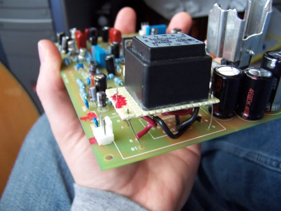
As promised, here's the stilt picture. I mounted the output transformer on vero, and then put it on stilts above the PCB. I then connected like I said:
For the output transformer primary I connected S1 to point 1 on the PCB (which was the start of the winding on the Lundahl) I then connected both F2 and the shield to point four (which is ground) on the PCB.
Then on the secondary I connected S1 to point 6 on the PCB, and F2 to point 9 on the PCB. I linked the transformer as you said on veroboard.
Sound good?
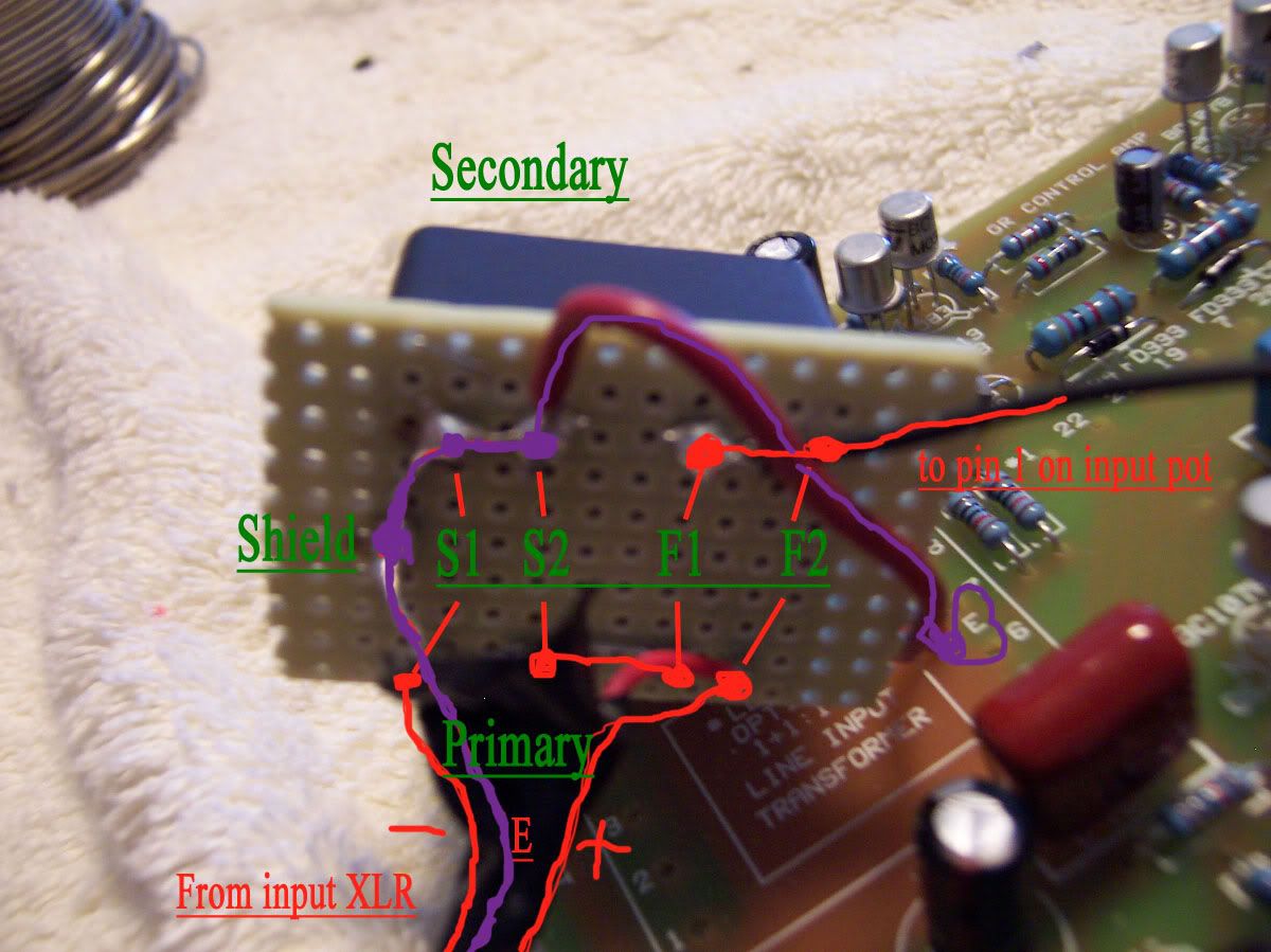
Next up will be the wiring of the input transformer.
For the output transformer primary I connected S1 to point 1 on the PCB (which was the start of the winding on the Lundahl) I then connected both F2 and the shield to point four (which is ground) on the PCB.
Then on the secondary I connected S1 to point 6 on the PCB, and F2 to point 9 on the PCB. I linked the transformer as you said on veroboard.
Sound good?
Next up will be the wiring of the input transformer.
")