MixBuzz1 Build/Support thread

GroupDIY Audio Forum

Help Support GroupDIY Audio Forum:

This site may earn a commission from merchant affiliate links, including eBay, Amazon, and others.
Got some mails. Lazy. But here are photos :)

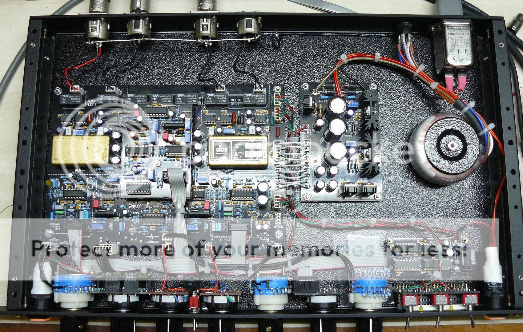
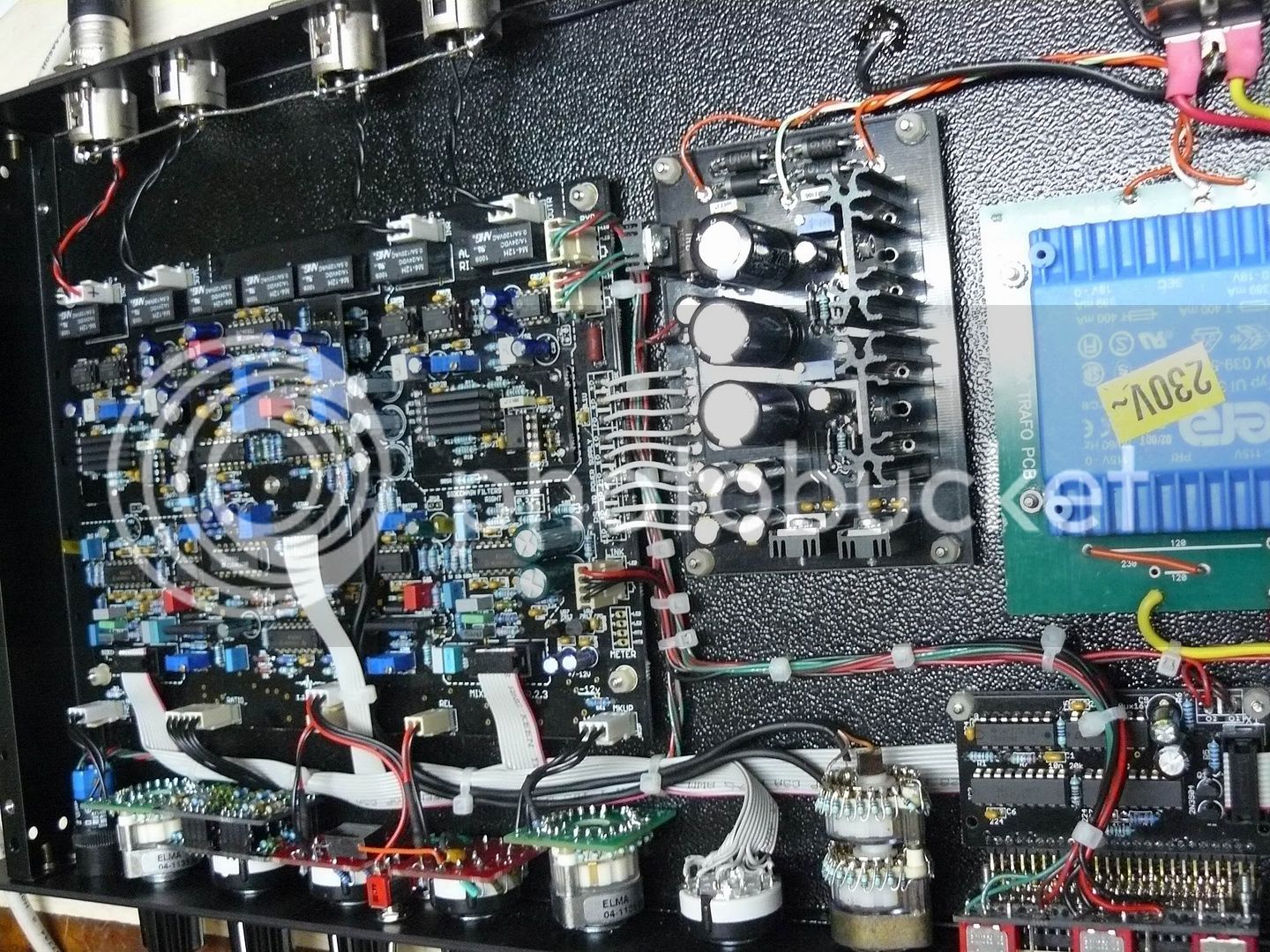
Pictures of stepped units I did some time ago. Can be helpfull. Have a fun!

The album:

http://s251.photobucket.com/albums/gg291/diy33609/stepped%20mixbuzz1/

Stepped attack/release (was asked 5 times at least by mail):

http://www.groupdiy.com/index.php?topic=41654.msg573975#msg573975

Using DBX202C gold can VCA's in MixBuzz1:

DBX 202C GOLD CANS
RXX APPLY TO BOTH L AND R (R100L, R100R)
R6 40K2
R2 1MEG...1.5 MEG
R100 710R
R4 JUMPER/FERR BEAD
R3 40K2
C1 5PF


Porn:

P1060853.jpg


P1060947.jpg

 
Second MixBuzz up and running here - bit different (nu VU, switches for attack and release) to my first one...


MixBuzz1SE_front_open_web.jpg

MixBuzz1SE_cabling_web.jpg

MixBuzz1SE_front_meter_web.jpg

MixBuzz1SE_front_switch_web.jpg


Here you can see the difference to the first one:
SumComp_Brigade_web.jpg

 
Really dig your designs and clean wiring on your mixbuzz chefducuisine. The led metering in the middle area for the first mixbuzz looks misaligned.
 
sorry
someone can tell me how to connect stepped switches for mix (DRY - WET)
I had a double potentiometer mounted but I would make a version with steps
thanks
 
chefducuisine:

Cannot stop watch this roboporn!!!!!! What a chick!!!!!

ilfungo: dry-wet switch, take a look on pcb, all is written.

Very important update.

Due to 90% of people who built this compressor did it with 11 steps attack and release switches, the new PCB's are done by this way.

All is same, but easier wiring.

http://ij-audio.com/downloads/MB1_docs_2_5.rar

+12V regulator's heatsink was changed to bigger one.
LM3914 LED current setting resisters were changed to lower power consumption too.

In case of whatever: use 12V relays with 700Ohm...2kOhm coil resistance, to reduce current consumption.

Front for use with Uraltone 23-step switches (the controls are bit moved to get space for 23-pos switches):

http://ij-audio.com/downloads/mb1_2_5ver9cdr.cdr

(saved in Corel version 9)
 

Attachments

  • attrel.JPG
    attrel.JPG
    308.5 KB · Views: 99
Mm... Yep! The next step is digitally conroled MixBuzz1!
Not kidding, BTW.  Any interest? Please post here:

http://www.groupdiy.com/index.php?topic=29771

Let's keep this thread clean for troubleshooting and tech-stuff hardcore :)
 
Hi

Anyone have that excel bom by evilcat? Link not work.

Email it to me, please: lassi.pitkanen (at) wmail.fi
 
Hi Mixbuzz-Builders!
I want to build the mixbuzz in a 1HE-case but i have trouble finding the 2200uF 50V Caps Low ESR with a height that fits...
All i can find is the Panasonic-Cap, but it´s 38mm and thats to much.
What did you use?
Or: is it save to use a 2200uF/ 35V-Cap? I have three that would fit...
Thanks
Chris
 
Or: is it save to use a 2200uF/ 35V-Cap?

Yes, if you use 2x18V AC power transformer. The voltage on caps will be within 25-30V, and it is OK.
 
Thank you Igor!
I use a 2x18V power-Trafo
One last question, just to be sure and because i have some trouble understanding it. My trafo reads:
Prim: black, black (thats clear, i understand this:))
Sec I: red, yellow
Sec II: blue green

If i understand you right...
"For 18-0, 18-0 transformer (two secondary's):
Connect 18 of one secondary to 0 of other secondary and to CT at power supply PCB
(this is the central point of 18-0-18); than, 18 goes to ~18.1; 0 goes to ~18.2. Hope it is clear."

...I have to wire the Trafo like this?

Red and Green go to CT
Yellow goes to 18.2
Blue goes to 18.1

EDIT Or: Red to 18,1, yellow and Blue to CT, green to 18,2...
I think i got it:)

It´s probably a dumb question. Sorry...
Chris


Blue/green/etc does not says anything. We need start/end of windings.
To avoid guessing. First, sheck if there is a datasheet of transformer.
Than, sec1 + (or start) connected to sec2 - (or end) and this is CT.
If there is no datasheet of transformer, use inductance meter.
Disconnect trafo from everything; measure one secondary; than connect secondarys;
if they connected right, summary inductance will be 4 times higher than single secondary.
 
Luax said:
Hi Mixbuzz1 enthousiasts!
Some days ago I started assembling the boards for my complete mixbuzz1 build.
So far most of it is pretty clear.
Exept that with the parts I ordered from Igor I got the 23 step potmeters with a lot of resistors.
Is there somebody that could shine some light on how the resistors go in the potmeters in the correct way, and how to wire them properly?
I couldn't find much about it. I'll keep you updated in my progress!
Cheers!
Check some posts before, you have pictures of 2 units with stepped switches.
Solder resistors to switches to get stepped linear 10k pot. I think it is clear.
 
One of dudes (he isn't a member of our forum) asked for Mouser/Farnell or Digikey part list.
I used to buy the parts from local suppliers, taking best of their stock, and the rest is usually Fasrnell order.
But, maybe, somebody have a parts list in organized form with cat nr's to help him?
 
Yes, I have something like that: an excel BOM, with mostly Mouser part. Lot of member emailed me and I send them the file. Does anyone have an idea where I can host it?

Ben
 
Woa! Dats sounds cool, Ben. Please send it to igor_jazz at yahoo, I will host it at ij-audio.com/downloads
 
Back
Top