Neumann Vintage U87 Clone : Build Thread.

GroupDIY Audio Forum

Help Support GroupDIY Audio Forum:

This site may earn a commission from merchant affiliate links, including eBay, Amazon, and others.
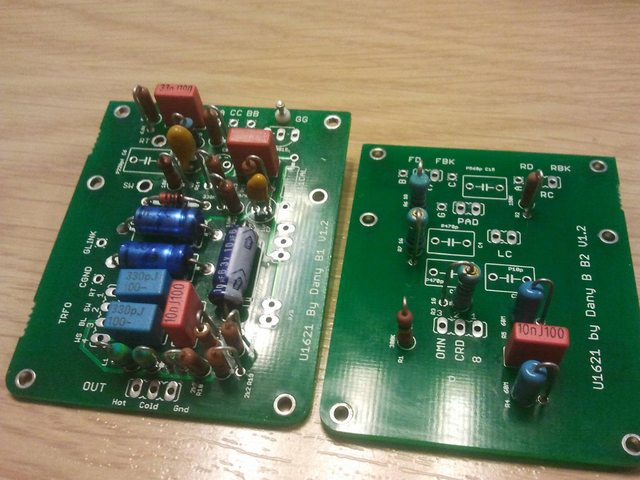
+1 on showing us some clear pics.
You have a serious technical issue,not only hum.Since the crackles sound kind of rhythmic it seems to be at least a capacitor related thing (remember that the capsule is a cap too).
Do the initial voltage tests first,then go from there methotically.
Are there any voltages off or do they seem to be incorrect?
Do the issues appear to happen when the mic is warmed up,is it different right after switching phantom on?

Udo.
 
No problem, i am not an engineer, only know basics and learning through each project i make :) (and english is not my native language)

The rythmic issue disappeared.. i realized it happened when the soldering station was on.

The ground i measured from the mic and mod is pretty good, but i dont know if something is missing. The only problem now, is that after a certain time, the mic, stops working and only makes hum, i will take some photos, i think every component is in its place, since its working now and sounds great, it has a very low noise(well, the same happens if i run the mic without the outer case, and if for example my finger is near the fet, noise get worse).

i will be checking voltages and post what happens.

Another question, in the pcb there is a CGround pin, where should i connect it? since in the jack of the mic, it connects pin 1 and 4(chassis ground)?
 
Graph said:
No problem, i am not an engineer, only know basics and learning through each project i make :) (and english is not my native language)

The rythmic issue disappeared.. i realized it happened when the soldering station was on.

The ground i measured from the mic and mod is pretty good, but i dont know if something is missing. The only problem now, is that after a certain time, the mic, stops working and only makes hum, i will take some photos, i think every component is in its place, since its working now and sounds great, it has a very low noise(well, the same happens if i run the mic without the outer case, and if for example my finger is near the fet, noise get worse).

i will be checking voltages and post what happens.

Another question, in the pcb there is a CGround pin, where should i connect it? since in the jack of the mic, it connects pin 1 and 4(chassis ground)?


Cground is for the original transformer with core ground.
You can omit/ leave it be.

*ah found my notes* lol
 

Attachments

  • image.jpg
    image.jpg
    305.7 KB · Views: 21
Great! :)

Well.. i left the mic with phantom power for several hours and i didnt have any more problems :) it seems it is a successful built one.

Is it normal if i change the polarity there is a clip noise? I was thinking, if the polarization is changed within a switch, it will generate a noise like a phantom power(sorry i have only used condenser mics with fixed cardioid)

Thanks Dan for this great project!!
 
Graph said:
Is it normal if i change the polarity there is a clip noise? I was thinking, if the polarization is changed within a switch, it will generate a noise like a phantom power(sorry i have only used condenser mics with fixed cardioid)
Yes,even the originals do so.Just turn down or mute the monitors before changing the pattern.
Remember that in cardioid only the front capsule is working.Switching to another pattern means the back capsule is switched on immediately will get around 40vdc polarization voltage,this will cause the pop.

Or do you really mean the polarity or better said: phase switch on the mixer/preamp?
Here no noise should be audible.

Best,

Udo.
 
Hi Folks,

It's been a few months since I finished my U87.  Been using it a bunch and digging it very much.  Thought I'd post a small clip in which vocals and chorus electric guitar were cutt with the mic for those that are interested.  It is processed so not a good example of the raw sound of the mic but a product of.

Build and signal path info:

BeesNeez K8

AMI T13 

Styrene Caps

-----------------

Vocals:  Mic - Sound Skulptor MP73 - Onyx 1640i - Cubase - Equality (minor subtractive) - IK 1176 - Waves J37 - IK LA2A.

Guitar (Deluxe Reverb):  Mic - Sound Skulptor MP12 - Onyx 1640i - Cubase - Equality (filtering) - IK LA2A - PSP Spring

http://www.mediafire.com/download/onzqzlknaggxeun/

-----------------

The Vocals in this track were also cutt with the mic but it was a while ago now and all I remember about the signal path was it was also: Mic - MP73 with extensive ITB processing:

http://www.mediafire.com/download/1e19fh4s97277ij/
 
Hi all,

building the D87 now per "Original" specification.
Actually this is my first serious DIY project (built a DI before).
First of all I want to thank Dany for the work he put into this and Chunger for his amazing photo build thread.

I got this far:
OQuh19kl.jpg


Now from all the talk about IDSS of the JFET I only got that I have to measure it but I didn't understand what IDSS is better lower or higher.
By the way I purchased the JFET that is in the BOM now, its the 2N3819 from Central Semiconductor, not the Fairchild. I hope that's right.

I measured the three JFETs (thanks Matador) and they came out 7.5mA, 12.1mA and 14.3mA.

Which one should I use?

Appreciate your help.

Cheers
Moshe

 
lkipod said:
Now from all the talk about IDSS of the JFET I only got that I have to measure it but I didn't understand what IDSS is better lower or higher.
By the way I purchased the JFET that is in the BOM now, its the 2N3819 from Central Semiconductor, not the Fairchild. I hope that's right.

I measured the three JFETs (thanks Matador) and they came out 7.5mA, 12.1mA and 14.3mA.

Which one should I use?
Hello Moshe and welcome to the forum.

The lower the IDSS value the more gain you will get,but less headroom.
Anyway,the 7,5mA fet looks very nice.

Best regards and have fun,

Udo.
 
kante1603 said:
lkipod said:
Now from all the talk about IDSS of the JFET I only got that I have to measure it but I didn't understand what IDSS is better lower or higher.
By the way I purchased the JFET that is in the BOM now, its the 2N3819 from Central Semiconductor, not the Fairchild. I hope that's right.

I measured the three JFETs (thanks Matador) and they came out 7.5mA, 12.1mA and 14.3mA.

Which one should I use?
Hello Moshe and welcome to the forum.

The lower the IDSS value the more gain you will get,but less headroom.
Anyway,the 7,5mA fet looks very nice.

Best regards and have fun,

Udo.

Hi Udo,

thanks for the warm welcome.

So with the 7.5mA FET I guess I will get the best blend of gain and headroom?
And also if I want to match two mics I understand from this that the IDSS should be identical?

Cheers
Moshe
 
lkipod said:
Hi Udo,

thanks for the warm welcome.

So with the 7.5mA FET I guess I will get the best blend of gain and headroom?
And also if I want to match two mics I understand from this that the IDSS should be identical?

Cheers
Moshe
It depends on what you want.The "usual" values are indeed in the lower than 10mAs area here.
I have built four,all from 8 to 10,very happy with them.If you ever run out of headroom you can still use the pad which will give you another roughly 10dB.
For matching yes,should have the same values.But what is more important is to get matched capsules and transformers since these are the most responsible parts for the sound.
Mustn't match too precise,the originals don't either.Levelwise you will match them on your mic preamp gains anyway.

Best,

Udo.
 
kante1603 said:
Jesus,that´s not good......

You did things wrong,no doubt-or have a damaged fet,or built something else.....who knows.
Forget about the switches by now.
Did you do the initial voltage tests,did you follow all recommendations here and did you read the whole thread?
We need this as a first basic info from you.
After that we can proceed.....
The mentioned cap (50pF or so) in the bom is not needed for calibration.
Btw.,the scope method is the best by far,but at least we should get this mic up and running even the other way.

Meanwhile let´s get things sorted.

First confirm the phantom is o.k.,measure the voltage coming from the babyface at the female xlr of the breakout cable.Set your dmm to dc and measure between xlr pins 1&2 as well as 1&3.Both readings should be identical,around the 48vdc area.What do you get?

Then lift all seven switch wires from the pcb points and put them aside,we don´t need the switches at this moment.The mic is now-given the capsule is attached-in just cardioid mode (only the front capsule is working now),hpf and pad are disabled.

If phantom is o.k. give it a listen again,did something change significantly?

Also what you can do is measure the xlr pins 2&3 with dmm set to ohms-what do you get?

This is my trial to shoot out several parts being not proper or damaged or hooked up the wrong way.

With the switches desoldered it could be useful to have some pics from the pcb,both sides,if possible from the solder sides too.

Please report back here,

Udo.

Hi guys. I gave up on working on my u87 this summer, but today I picked up where I left off...

taking the ground pins ohm test i got a reading of 28.7 ohms. What does that mean? I will proceed to troubleshoot and swap out the fet which I have likely damaged when I wired up the 7 switches wrong (or at least that's what I think had happened). All 7 switches are currently disconnected and I am testing/calibrating in cardiod. Hopefully I can  salvage a good mic.

Thanks for all your help - Andrew
 
Got it working!!! switched out some sickly soldered leads with new ones. Switched out the fet, grounded more, and coated the inside of the b2-pro tube with electrical tape. No hum. Works like a charm now just need to adjust trim and replace with a resisteor plus get switches working. But man I have sound  :D yaaayyyyy!
 
Hi Andrew,

don't know how you tested grounds,from which point to where.
But the value in ohms must be zero over and amongst all ground points.
If the measurement was across pins 2 & 3 on the xlr then it is o.k.(dcr of the transformer).

Also what seven switches are you talking about?This mic has three......
Did you do the initial voltage tests?
No pics?

Udo.
 
Hey Udo, I did mean sickly "soldered leads". I started building my diy u87 with less than adequate tools; I didn't have a good wire strippers nor a clippers that would cut leads flush to the pcb. This created a huge headache of problems.

As for the measurement I posted that was from pins 2 & 3 so it was all good! I did not test via my dmm ground points but when I connected everything up it worked like a charm.

I will be posting pics about how i made the b2-pro body suitable for this build considering it was quite a hassle to work in, but I figured I'd take the pics during my 2nd diy u87 build considering I bought 2 kits of diy u87 parts. I can even make a brief step by step guide for working with the b2-pro body.

Still gotta install the switches.. none are installed as of yet, but dang this thing sounds awesome in cardiod. I used an AMI T13 transformer with an rk87 capsule, Danny's boards and capacitors. SOUNDS AWESOME SO FAR :)
 
Hey, fellows,

I'm having some trouble with my build.  I have not yet connected the transformer or capsule, but all other components are soldered to the boards.  I am attempting to bias the FET.  However, if I connect the microphone to phantom power (coming from my Apogee Duet) and attach one of my multimeter leads to the jfet drain and the other to the ground, and measure DC voltage, I get around 1v.  The most I can get after adjusting R11 is 1.54v.  I certainly can't get 11.5v.

Can anyone tell me what I need to do to troubleshoot this?  My electronics knowledge is very minimal so I'd need layman's instructions.  I know there's a way to measure the voltage to the Zener diode, but I don't know where to attach the leads for that.
 
You make your measurements with the black DMM lead on ground and use the red DMM lead to probe around.
Go back to like page 5 of this thread and look for a quote Dany posted with some typical voltages measured from different components (L1, L2, Zener...etc)

Are you sure you're measuring the FET drain as the source voltage will be around 1-1.5 VDC

Dave
 
Following this fellow's lead, I am checking various points on the board.  My black lead is attached to ground, my red lead is attached to the following:

Hot: 47 V
Top of L1: 47 V
Top of L2: 47 V
Top of R18: 47 V
Top of R19: 46.6 V
Bottom of R17: 46.5 V
Top of R17: 22.8 V
Zener Cathode: 22.8 V
Zener Anode: 0.00 mV
FET Drain: 1.148 V
FET Source: 1.133 V
Top of R12: 44.8 V
Top of R13: 1.148 V


I think I have R12 and R13 backwards.  If so, then it's actually the top of R12 that reads 1.148V and the top of R13 that reads 44.8, because I have them swapped.  I am using the D-87T and the silkscreen overlaps, making it difficult to tell which is which.
 
Yep, that was it.  I swapped R12 and R13 and now after adjusting R11 I get 11.5v at the FET drain.

Thanks for the help!
 
Since I'm at this step already, can someone give me some instructions on how to better bias the FET?  I'm using a potentiometer at R11 to keep things adjustable, and I've done the basic task of adjusting that potentiometer so that the voltage to the FET drain is about 11.5 volts.  However, I know there's a better way that I think involves using an oscilloscope?  If someone could give me some step-by-step instructions on that process, I'd love to learn how to do this properly.  As I said, I'm pretty new to this.
 
Back
Top