oh boy so I am hoping yu all can offer a little guidance on this. I am using a B**inger B2-Pro for my build. Naturally I bought it specifically for this project so I could have switches. I have hit somewhat of a roadblock which I hope you gents might have a solution. Unfortunately the switches in the B2- pro I am using is not like the one Udo had made a tutorial for. Even if I wanted to just get rid of the factory switchboard the switch pcb Poctop has made won't fit inside the mic. sigh... But it doesn't look hopeless.
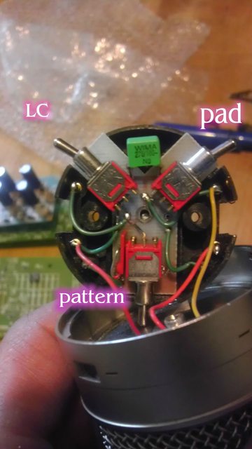
What I need is maybe some verification on which lead is which coming out of the switches and where I can tie them. I imaginer i should probably lose that green wima?? Should I just run separate wires from each switch and the capsule to the pcb?
I marked which switch is which.
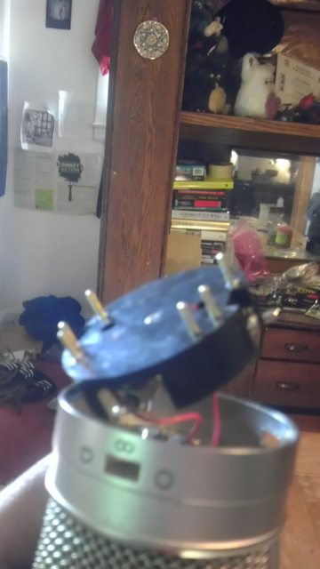
And this where it comes out the bottom through those pins. Notice each in sets of two.
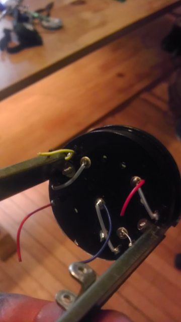
And this is where they finally end up and connect to the stock pcb. I am pretty sure tracing I could figure out which wire leads to where but as of right now I am not positive. I don't know what those grey wires are for exactly either.
Is there any chance I can just use the wires coming out of that final point? Should I run wires off of the switch pins in the second pic to their designated points on the pcb? Anyone have this version of the b2 that could offer up what they did? Thanks. Oh and its a cool project. Thanks Poctop.


")