Planning my BA-6A

GroupDIY Audio Forum

Help Support GroupDIY Audio Forum:

This site may earn a commission from merchant affiliate links, including eBay, Amazon, and others.
or £25 worth of resistors!

Really?!?

I buy from Newark over here and they are the same as Farnell UK.  25UK pounds would buy me a years worth!  What type resistors did you use?
 
I buy mine from RS, and the minimum order for a lot of the values I needed were 10, which came to about £1 per 10.  24 steps later and you're looking at around £25.  The values specified on the Goldpoint website for a 25k aren't common values, so I didn't have any lying around.
 
DaveP said:
Letterbeacon,

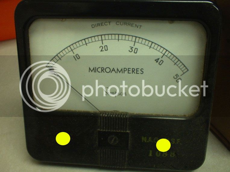
50uA is just about the most sensitive meter you can get and putting low res meter ranges across it might bend the needle.

Best to connect a 1.5V battery with a big pot in series, say 50k, that means it can't pass any more than 30uA.  Turn the pot until you get 50uA FSD. then measure the voltage across the meter.  Meter V/50uA  gives you the meter resistance.

Play safe with that meter.

best
DaveP

I found some time to try and work out what value shunt resistor to get my 50uA meter working with the BA-6A.  If someone could quickly check my maths to make sure I haven't gone wrong anywhere, that would be great!

My meter reads 0-50uA FSD
The BA-6A meter reads 0-500uA FSD

So I measured the voltage across the meter with 3v connected to it with a 100k pot in series.  Voltage across the meter when reading 50uA  = 0.89V

meter volts/ 50ua = meter resistance

.089/ 0.00005 = 17800r

How much current I want to shunt:

Is = Itotal - Im

450uA = 500uA - 50uA

So now to figure out the shunt value:

Rs = Rm / (Is/Im)

1977.77 = 17800 / (450/50)

So I should use a 19k8 .1% resistor in parallel with my meter to get it to read 500uA FSD.

Does that seem right?
 
Matt,

If your voltage across the meter figure is correct, then a 1% 2k resistor will do it.

0.89/2000=445uA
0.89/17800=50uA
Total 495uA

That is within 1%, the scale on the meter won't be that accurate (0.89V is only 2 significant figures so no point in getting a better match)
best
DaveP
 
Brilliant -thanks a lot!

Just while we're on the subjects of meters.  I would like to add a couple of LEDs in mine as it doesn't come with a lamp.  I was planning on carefully drilling two holes in the back to mount them both.  If I drill the holes in the back at the points I have marked in yellow, am I in danger of hitting any important parts?  From taking it apart, it looks like it's just plastic at those points, but I wonder if anyone else knows otherwise...

meterled.jpg


Thanks!
 
Matt,

You may need some at the top too.

Try to get warm white LED's the regular white ones give a very harsh light that spoils the vintage look.  They each drop 3.5~3.6V and need a series resistor, aim for 20mA.

best
DaveP
 
Thanks for the tip.  I was going to use yellow LEDs, to make it look more like a lamp, but I'll give the 'warm white' LEDs a try now.

Just looking at the schematic, it looks like R60 (on the very left of the diagram) is already behaving like a shunt.  I should keep that in and wire it in parallel with the 2k shunt, shouldn't I?
 
Matt,

Yellow LED's might be better, but they operate at a lower voltage drop, I used white because my company makes the phosphor for them and had them kicking around.

R60 the 82ohms should still be used as you just fooled it into thinking its shunting a 500uA meter.

best
DaveP
 
At some stage, when I've finished the stock circuit, I would like to add a threshold control to the limiter.  I've seen it on DaveP's BA-6A and on gary o's unit, but I'm having a hard time figuring out how I can add it to mine.

I have two questions:

It looks like DaveP has added a 100k pot to control the amount of voltage biasing the side chain (schematic attached).  But I'm following the original RCA schematic and I think that if I do the same thing, I'm going to affect the tap that biases the 6.3VAC heater supply.  Is that the case, and if so, is there any way round this?

Also, I'd like to add a scale to go round my Threshold control.  How do I calculate the values on the scale?

Thanks very much!
 

Attachments

  • 29ejc7t.jpg
    29ejc7t.jpg
    60.9 KB · Views: 26
Matt,
On the original schematic, you have R44=56k and R45=33k, together they make 89k, so what you do is put in a suitable 100k pot instead of those two, with an 820k resistor in parallel across the outer lugs and take the wiper to your 6H6 circuit.  820//100=89

What scale were you looking for?  Voltage or compression?
best
DaveP
 
Thanks Dave -the penny's just dropped!

As for the scale, I was thinking maybe dBu like you get on the 33609, but then looking at the Fairchild, it just has seemingly random scale of 1-10 in no particular unit, so I may go with that.

Just out of interest, how would I work out a dBu scale?

Thank you!

 
To a certain extent the input control and threshold are interchangeable, which is why you often find the threshold fixed.  At low input levels you would need low threshold voltages to commence compression and vice-versa, best to stick with a nominal scale.
best
Davep
 
Dave will have to comment on the usefulness of the 0V position on the threshold.  Some vari-mu types freak out at 0V, and need some minimum value stop resistor to keep bias present.  I don't know about here. 

Threshold is ratio, and vice versa.  10dB pad removal test to determine ratio.  Collins 26U manual describes the full method.  I'd label for ratio rather than threshold. 

------edit------

Quoting from bad memory.  The Collins test differs from the 10 dB input comparison method.  It is as follows:

Attack and release both set slowest (applicable to 26U-1), adjust input level to 1dB GR past threshold, increase signal level until output increases 1 dB, find ratio of input level increase/output level increase. 
 
Doug,

That pot I described would not have a minimum of 0V as there is R46= 15k resistor between it and ground making the minimum 22V.

I haven't done the 26U pad test yet so can't pass it on personally!
best
DaveP
 
I tentatively powered it up today, and nothing exploded -hooray!

It looks like my B+ is a little low -I'm aiming for 285VDC, but at the moment I've got 250VDC.  I have 47r limiting resistors on the rectifier anodes, and my lowering the resistance here I should be able to get something nearer 285VDC.  I don't have any lower values with high power ratings at the moment though, so I tried putting a 47r in parallel with each limiting resistor, to bring the resistance down.  For some reason the B+ dropped further down to 230VDC.  Why is this?  Surely having less resistance (now 23.5R) should lower the voltage drop, not raise it?
 
As PS resistance goes down B+ rises and so does current draw.  The intersections are not easy to interpolate off the cuff.  The constant is your 6V6 cathode resistor.  Raising it will raise apparent B+ but will shift bias point.  It may not matter that much in either case.
 
Matt,
If it goes down with ~24 on each leg try putting the 47's in series giving ~100 on each leg, it might be your TX needs more resistance to work into.  There is probably an optimum resistance for your rectifier TX combo and you need to find it.

If you can't get any better than that, then as Alan says, you can only reduce the current draw by increasing the  cathode resistors, say from 330 to 360 or 390.  It won't affect the perfomance at all.

There is another possibility; check the current through each output tube and make sure they are in reasonable balance.  If there is excessive current with no signal then there is an ultrasonic oscillation drawing extra current, check with scope.

hope that helps
best
Dave
 
Thanks chaps, I'll have to have an experiment when I get some time this weekend.

Incidentally, how hot should the 5R4GY be?  At the moment it feels like a light bulb -i.e. I can't touch it for more than a couple of seconds because of the heat.

EDIT - I'm so close to finishing the wiring on this I can almost taste it!
 
Matt,
The spec on most of those tubes is around 200C! so I would keep my mitts off any large tube when its hot!  Only small signal tubes like 12AX7's with 0.3A currents should be handled hot.  Back in 67 an idiot knocked a pint of beer over my 100W PA amp whilst we were playing in a pub, one hot Mullard EL34 went out with a blue flash, I was lucky it didn't get the other three.
best
DaveP
 
Back
Top