The official G9 help thread

GroupDIY Audio Forum

Help Support GroupDIY Audio Forum:

This site may earn a commission from merchant affiliate links, including eBay, Amazon, and others.
Hey guys. I built a G9 for a colleague recently, and it works very good, except the phantom power psu. I got about 90V to ground after the voltage tripler, where 60V  should be normal. Because of that i don't get the phantom voltage down to 48V (it's 56V actually). Any ideas, what i could to do?
 
Did you check power transformet connection ? Is there 15V on PCB connector ? Maybe you connect wrong wires and there is 30 ?
 
You could remove/bypass one of the stages and just go with a doubler, should drop you down to a usable voltage. Remove C26, bypass D11, D12
 
I appreciate your help. Thank you very much. So i took some more measurements. The input voltages are 272V and 2x 16V AC. After R33 i have about 342V DC to ground, but the regulator takes care of it. At the tripler, i habe 18V after D8, 36V after D9 but 54V after D10. Taking one stage out might solve the problem, but not the cause. Should i search somewhere around D10?
As i'm actually very pleased with the unit I attached a picture =)
 

Attachments

  • g9.JPG
    g9.JPG
    324.3 KB · Views: 120
I am with glover... I think the place you need to start is with the AC input voltage you are FEEDING the multiplier. On your board (thanks for the pic) there are two blue wires going to a black connector for 15VAC.  It would be VERY informative to have a measurement of the AC Voltage at that connector.

If that is too high and the the transformer is putting out a LOT too much then you should probably have some heat problems with the 12V regulator as well, because it would have to dump more heat.

Another possibility is the wrong value in Zener diode D6 (or even wrong values or bad solder joints in R41, R39, or R40 or the PR1 trim pot) most of which could screw up the 48V regulator.

You have  a huge heat sink on the regulator, so I am not sure you would notice the heat.


bb

tobi.pl said:
I appreciate your help. Thank you very much. So i took some more measurements. The input voltages are 272V and 2x 16V AC. After R33 i have about 342V DC to ground, but the regulator takes care of it. At the tripler, i habe 18V after D8, 36V after D9 but 54V after D10. Taking one stage out might solve the problem, but not the cause. Should i search somewhere around D10?
As i'm actually very pleased with the unit I attached a picture =)
 
Yeah, i have to work at my color scheme for wiring my gear, but i had nothing available but blue wire ;-) The input Voltage is 16V AC, so thats fine. The 12V rail is also ok...
Checked for a bridge between D10 and D8, but nothing... Still 90V after D12 (1,5 times the value it should be :-( )
 
No apologies needed.  I can trace the blue wires. 

Two thoughts:  1) secondary coil voltages - can't make them make sense. 2) Load?

First - secondary coil voltages...

There are 2 different 15V AC screw connectors on your board, one green, one black, coming off (presumably 2 different secondaries on the mains trafo) are they both at 16V ish?  or have you tested only the green one?  The 12V rail is fed by the GREEN one, the BLACK one is the one we want to look at.

The reason I ask is that some of your measurements indicate that one of the secondary coils may be a bit higher than 16V. I expected your 15V stepped back up to 220V AC, but you are stepping your (unknown? 16V? ) back into 272V - That step up makes me suspect one of your windings is not 16V (but I can't do the math without understanding what transformers you are using, Munich implies 220 I guess).  Anyway the same secondary driving the 272V is driving the Voltage multiplier (the one on the BLACK connector near the edge of the board).  So that could explain the 90V maybe.

Can you tell us the make and model or specs of the transformers?  Munich is 220V right?

Here is the second debugging thought... Load.

Voltage multipliers are sensitive to load, so one question is to make sure you don't have an open that is reducing the load.

Basically without ANY load the voltages just stack, you seem to be stacking 18V's and if there is no load on the "tripler" then the cap's stay charged on each alternating cycle and so it looks like it will stack 5 of them - one on each cap - so you get 5x18= 90V.  But usually the load drags these down (since the only get charged every other cycle, and only to the extent the the ones above are still charged.  The more multiples, the less current capability)  So I suspect an open - or a much too high resistor value somewhere - is reducing the load

Not sure I understand the circuit but I think this is what to check:

1) R40 and D6 dump enough current across the Zener to leave the R40-D6 junction at 56V exactly.  If not then R40 is open, D6 is Open or D6 is fried (probably not, you are seeing 56V on output).

2) The pot PR1 and R41 form a divider that allows the base of T1 to be set to 48.7V or so.  This value is stabilized by C22, if there was an open for instance the bottom of R41, the voltage would float up to the 56V (which you are seeing on output).  So check the voltages there and the continuity.

R42 provides a small load (I think this is so that leakage doesn't allow C23 to float up above the base value  ...  not really sure), if it was open there would be no load and again C23 it would float.

Maybe the pot is bad, perhaps open on the bottom and has continuity on the top.  Or that the bottom or top of R41 is open.

My bet is if you turn it off and put an ammeter between the top of the pot and ground it is open.


But any open after c20 back there could cause a problem... or a too high value.... maybe you don't have any load on the 48V supply because the 10K resistor has a bad solder joint?  Or is 100K or something?  Or perhaps R39 is way too high should be 100 ohms.. is it 100K or something? 


Hope this helps, let me know.


Thank you for your help bruce!
First and secondary coil voltages were allrigt. Actually, we're at 230V at Munich (they changed it from 220 to 230V ;-) ), so 16V at the secondarys was alright. I used a 12V step up transformer (as i had problems with the HT voltage with my first G9 build), so the 272V (or something in that range) were also alright. I was so fed up with it not working, that i redid all the solder spots in the 48V section and exchanged all the diodes. As i looked at the new Zener diode (wrapped in farewell plastic with a label that said zener 56V) i saw that it had ph4148 on it (maybe it was a 1n4148?) so i searched for a 56V one in my spare parts. Now the phantom section is at 48V exactly =)
 
That's great.

I have done the wrong diode thing!  (I think I exchanged about 20 messages with Jeff Steiger once, all the time insisting I had the right diode, only to find I had switched a Zener and a 1n4148!) that might have been it.  I guess selling 4148's as zeners is a pretty good way to make money.

The multiplier diodes (if bad) would have made the voltage lower not higher so they probably were fine.

Since you had 56V before, you probably had a good zener in there to start, so I think probably the solder point touchup was it.  The adjustment pot would have done absolutely nothing if that was the case.

Anyway great job, and thanks for following up.  I love the debug process and am always curious about the outcome but sometimes I never hear back (probably because nobody wants to read me ramble on).

So now you can see how it sounds!  (or be drawn back into the vortex and build something else!).
 
bruce0 said:
That's great.

I have done the wrong diode thing too!  (I think I exchanged about 20 messages with Jeff Steiger once, all the time insisting I had the right diode, only to find I had switched a Zener and a 1n4148!)

So now you can see how it sounds!  (or be drawn back into the vortex and build something else).

I think it'll be the latter. I already testet it with a SM57 and it worked fine =) So there will just be a test if it withstands three hours of recording and go to it's new owner, who records the concerts we play with our orchestra. But there are two V672/2s that need to be tested and racked...
 
Hi everybody !

I'm back with my G9 and I need your help  :p

I'm trying to find the source of a 100Hz noise on the outputs. Even with the outputs levels at 0dB, the noise is present. Everything is correctly grounded (if I unplug ground wires, a 50Hz noise appears when I turn on outputs levels). I tried with power transformers and caps out of the case but the noise still the same :/

Do you have an idea ?
 
HI Guys,


I have a puzzling issue, when i turn up the outputs to about half there is a low freq buzz introduced, when then turn up full the LF noise goes away?
obviously i can use this flat out but would like to rectify this if i can? :)

regards

Spence.
 
Hi,

Have just completed building this wonderful unit. Had to fix two small wiring issues...

Sending out 0dbfs from the Fireface set for +4dbU, I am able to get about -95db of S/N, performance I am very pleased with. have also placed magnetic field shielding from http://lessemf.com/mag-shld.html around the trafos, which probably helped as well.

Thanks for the opportunity to build such a great device.
 

Attachments

  • IMG_0312.jpg
    IMG_0312.jpg
    536.7 KB · Views: 92
Looks nice womper, where did you do the front panel?

A suggestion (probably not necessary) is that shielding can reduce electro magnetic noise but another way to reduce EM interference is to twist pairs of conductors that carry AC or would be sensitive to AC.  In order of effect the DI's, XLR input (I see you already used shielded twisted pair),  transformer primaries/secondaries (which radiate), output XLR's, and lastly DC wiring. 

You can find suggestions online but the basic gag is as follows:
Tight twists (3-5/inch), the shield conductor if it exists running alongside the pair (not in the twist).  Opposing pairs of power conductors with each other.

 
Thanks bruce0 for the tip. I haven't thought about doing that for the trafo wires, only for audio. Have used shielded ones for the input but found the space too narrow to work with the heavy shielded wire that I had, so opted for regular 3 short ones. Perhaps I could have crossed that one as well :)
 
May not make any diff, but given the effort used in shielding I thought I would mention it.  If you don't radiate it, no equipment can amplify it.  Where'd you do the FP?
 
FP, right. I needed to drill a hole of the top right on/off and a centre one for the light bulb.

This is from DIY-racked.com. List of cases at http://www.diy-racked.com/diy-talk/viewtopic.php?f=7&t=18
 
Hi again :) sorry for bothering you again.

I am modding my G9(which i made myself). I changed transformers, with toroidals and better caps for filtering(For 245, Nichicon KX 100uf 400v, and 12v, elna silmic II 1000uf 25v capacitors).

For now, i got great results, i have taken some images and measures with soundforge. Before the mods, i just had normal Transformers(some pages back there are some photos), i got a hum in 150hz 200hz ad harmonics which its gone now, but now i have some noise. The actual measurement was made from a native instruments Kontrol audio interface, through mic input, and for example a -50dBu 1khz test tone, gave me like a -20(or -25m dont remember quite well) db FS measurement.

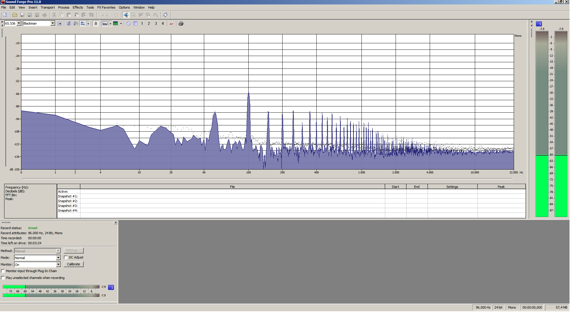
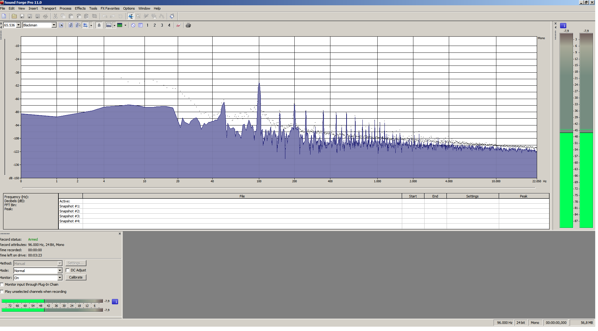
I made some measures, they are, with the preamp, output to the NI kontrol, One with without gain(all turn left) and master output closed, and other with master output all right(without gain also) and i got this hum, and measures.

WUGaxqy.png

QPdMBph.png


I havent drilled the holes for the new toroids yet, lots of spaghetti cables right now. Some pics:
http://i.imgur.com/3fRc7YX.jpg
http://i.imgur.com/cX3Ix07.jpg
http://i.imgur.com/FAUoU38.jpg
http://i.imgur.com/GwzJbBp.jpg

Any ideas on how can i at least get noise 10dBs quieter?
With my duet, noise was not an issue, with new trannys and caps, i guess noise wont bother, but when i am recording electric guitars through the G9, and apply Distortion plug ins, noise comes up.

I dont have this G9 in my studio right now, so i cant get more accurate measures, but thanks for any recommendation :)

Thanks and sorry for my english.
 
Graph,

It looks to me like you experience hum with harmonics which might be still related to the transformer. What I have used to lower that is special metal sheet that aids at reducing electro magnetic fields.

Have you tried taking the two transformers outside of the case to see if it makes a positive change?
have you also done the instrument in modification suggested earlier on the thread?
 
Back
Top